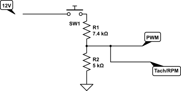
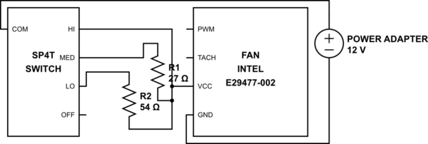
There were two basic types of PWM made. One type is an always off type that has a pull down resistor that kept it off when the main voltage is applied to the power wire. The PWM logic high of 5V controlled the on state of the fan. The other type is an always on, or free running which has a voltage divider network internally attached to the pin, and a logic low or grounding this pwm pin turns the fan off. The PWM logic low controls the off time state of the fan. The PWM fan can be controlled several ways. The most inefficient is the current limiting method the OP listed above, because the fan coils will oscillate from low frequency harmonics caused by the reduction of current flow in the fan coils. The basic PWM control is what I call the self idle circuit, that uses its own RPM signal to introduce the logic low for speed control:

simulate this circuit – Schematic created using CircuitLab
The fan's RPM sensor receives about 5V to operate the sensor. When the sensor pulls down the voltage when it conducts, the PWM fan interprets this as a logic low and temporarily tun off the fan until the voltage is above the normal TTL logic high threshold. The way a microcomputer controls PWM is with adjusting an oscillator signal to control this off state. The oscillator based solutions is just simulating what these micro controllers do, but at a less sophisticated methods by using 555 based timers and positive feedback oscillators.


