0
\$\begingroup\$

I don't have a strong ECE background, so I may ask many naïve questions.

I am building a probe station to measure pulses in a micro-coil, which looks like the following circuit. enter image description here
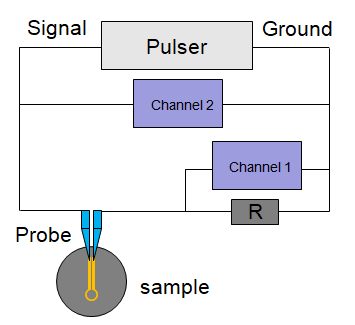
Because I want to measure the current flowing through the coil, but the oscilloscope only measures the voltage, I use channel 1 to measure the voltage across a known resistor and use Ohm's Law to calculate current. Some measurements are attached below. enter image description here

These 2 graphs show the measurements when probe is landed or lifted with 5V pulses. The sample has a large impedance, so when probe is in contact, the voltage change across the resistor is very small but still distinguishable.

enter image description here

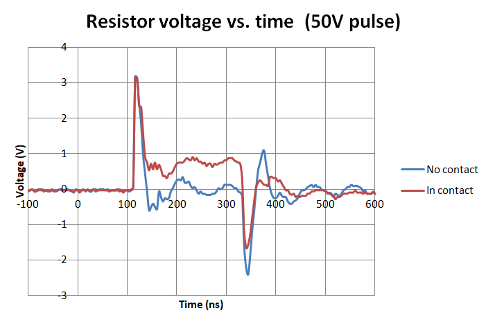
For a 50V pulse, I can clearly see huge oscillations when pulse starts and ends. My first question: is this ringing pulse? If it is ringing, what is the cause and how to prevent it?

My sample is a micro-coil connected with a pair of transmission lines. The transmission lines were designed to have LC=1/w^2, where rise time is about 1ns. I used the following links to calculate the inductance and capacitance of differential stripline, but them may not be the best choice. My second question: is there any better way to determine the dimensions of transmission lines for my case?

https://www.emisoftware.com/calculator/coplanar/

My third question: the pulser I use needs a 50Ohm load, does that mean the total impedance between signal and ground is 50Ohm? Or each piece in the circuit should be 50Ohm? Such as, each cable should be a 50Ohm coax, channel should be 50Ohm, and the probe and the sample should also be 50Ohm?

enter image description here

enter image description here

enter image description here

enter image description here

\$\endgroup\$
3
  • \$\begingroup\$ Please edit the question to limit it to a specific problem with enough detail to identify an adequate answer. \$\endgroup\$
    – Community Bot
    Commented Oct 19, 2021 at 23:03
  • \$\begingroup\$ Your first pair of charts do not seem to comport well with your second, merged chart. The blue line in the first pair, for in-contact and for no-contact, don't ever get anywhere close to 1 V. But in your second, merged chart, one of the lines does have a baseline quite near 1 V. No idea why I'm misreading. But that's what I see, just now. I'm sure it is my fault. But I need to see what you see. \$\endgroup\$
    – jonk
    Commented Oct 20, 2021 at 5:34
  • \$\begingroup\$ Hi jonk, I am sorry for confusing you. The first pair of charts were measured under 5V pulses, and the second merged one is measured under 50V pulses, so it is not the merge of the first pair measurements. Both voltages give similar pulse shapes, but 50V pulse shows a more distinguishable pattern, so I put it here. \$\endgroup\$
    – johnjl
    Commented Oct 20, 2021 at 16:24

1 Answer 1

1
\$\begingroup\$
  • all signal paths ought to be match loaded to 50 Ohms.

Since the probe impedance (pF) makes all the errors from tip capacitance and ground lead inductance around 8nH/cm you can eliminate most of this with calibrated probes only using tip &ring.

When both probes are on the same signal with this method A-B ought to give a flat line if both probes are calibrated.

But 300 MHz BW measurements are best done with matched impedance probes to the circuit or using SMA to BNC coax terminated with 50 Ohms . You will find twisting both 10M probes will also reduce CM inductive noise impulses.

As usual if the current sensor is small in R giving 50mV to 100mV max then the differential impedance will be low. Use this as a Rule of thumb for all current sensing. But specific V,I,Z(f) ought to be specified for all including the probe in your equivalent circuit. Impedance loading the coil to 50 Ohms is a good idea if you wish to load it for higher BW. but it depends on the Q you are assuming.

  • draw an accurate schematic of all parasitic elements and coil if possible with expected and actual results.

Some images of scope probe

enter image description here

TIP-Barrel test of oscilloscope

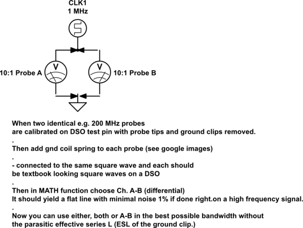
Logical schematic of two probes with gnd spring coil and exposed tip matched to same RF squarewave signal in A-B mode with a 0V flat line. This usually works up to 200 MHz. Above this SMA connections with 50 Ohm terminations using attenuation resistor series pads works better.

schematic

simulate this circuit – Schematic created using CircuitLab

\$\endgroup\$
6
  • \$\begingroup\$ Thanks for reply. Can you explain a little more on "with calibrated probes only using tip & ring"? How should I calibrate a probe? And what are tip and ring? \$\endgroup\$
    – johnjl
    Commented Oct 21, 2021 at 19:28
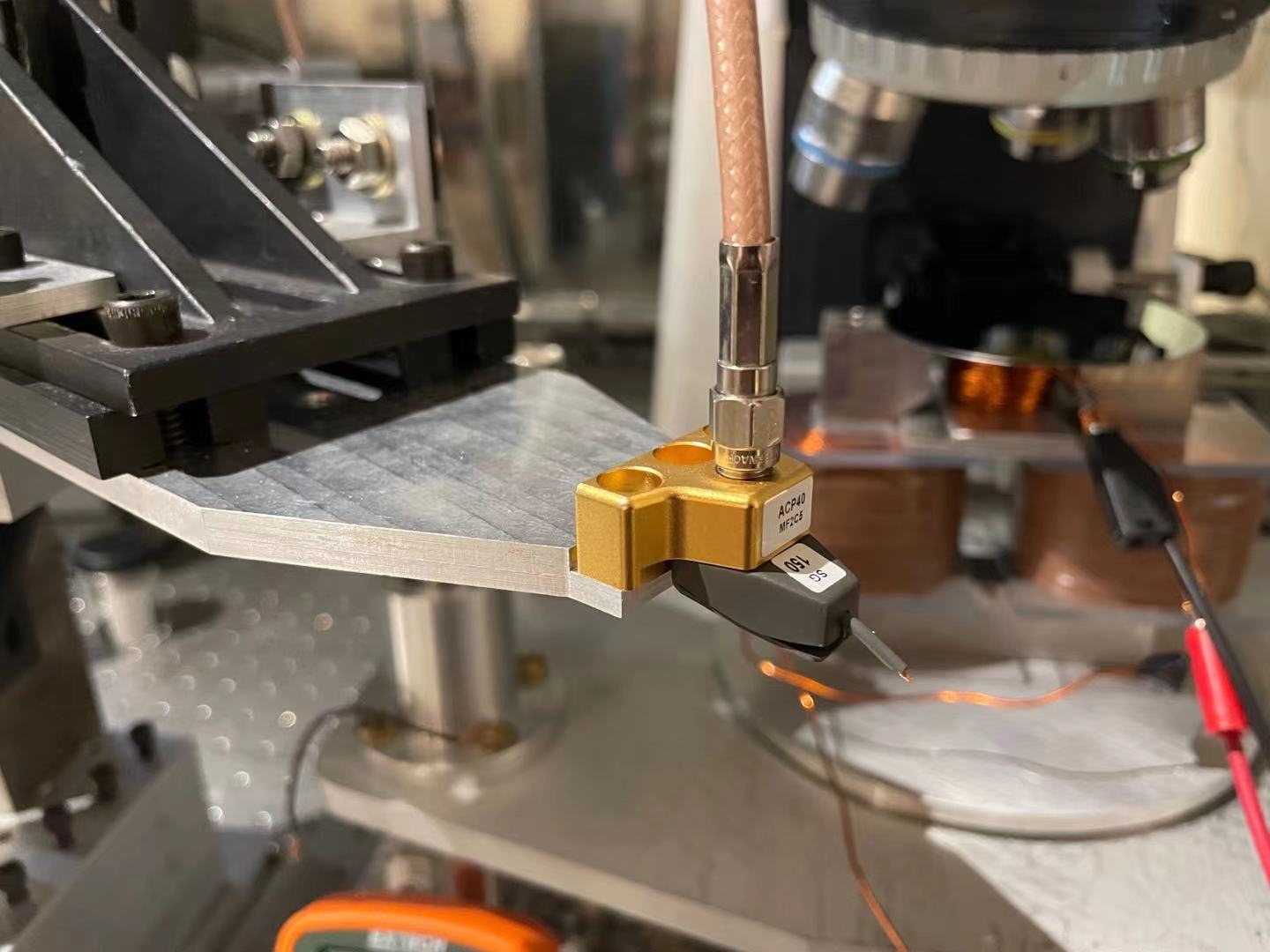
  • \$\begingroup\$ I appreciate your advice, but I don't think it will work for my case. I am using a ACP40 probe, which has a 150um pitch distance between probe tips, so It is too small to have a gnd spring coil. \$\endgroup\$
    – johnjl
    Commented Oct 25, 2021 at 16:08
  • \$\begingroup\$ Forgive my assumptions. Your probes are 40 GHz < 1ps 10 fF probes only 200 x better than what I was suggesting. Now perhaps you can show the design specs and pulser specs. is it a current pulse for a 50 Ohm load or a voltage pulser with some 50 ohm source. Also what R value did you use 1ohm? The probe station to measure pulses in a micro-coil ought to look like a ruggedised VNA-style DUT PCB with ground plane with >> 1GHz flat BW with a parallel Thru strip identical to the DUT strip what are L/C=? , LC=? and SRF. \$\endgroup\$
    – D.A.S.
    Commented Oct 25, 2021 at 22:02
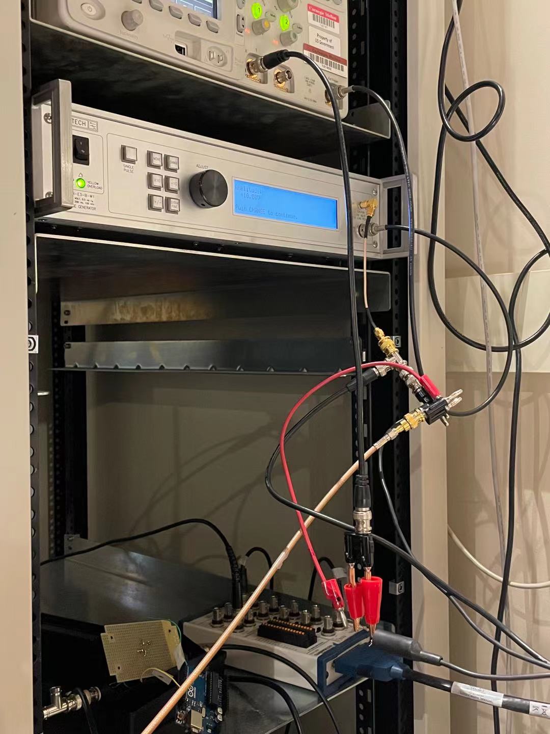
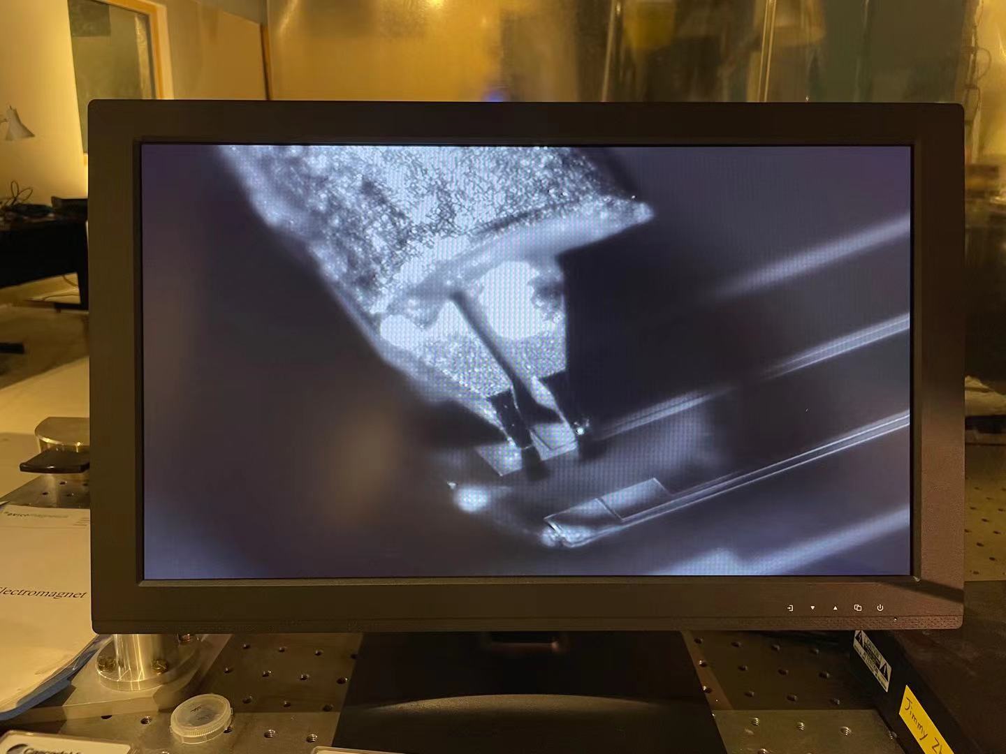
  • \$\begingroup\$ A picture of your platform with pulser and DUT are worth a thousand words. Also define your goals and tolerances \$\endgroup\$
    – D.A.S.
    Commented Oct 25, 2021 at 22:03
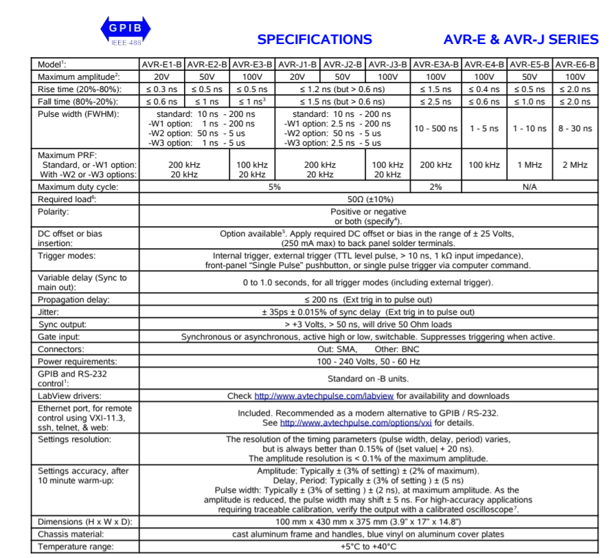
  • \$\begingroup\$ The pulser I am using is AVR-E3-B-W1, which is a voltage pulser with 50Ohm load. It provides up to 100V pulses with maximum 200ns pulse width, at 0.5ns rise time. The R I used is 5.1Ohm. My goal is to generate a pulse of magnetic field from the micro-coil by measuring the current flowing through the coil. The current can be determined from Ohm's Law, by measuring the voltage across the resistor R. \$\endgroup\$
    – johnjl
    Commented Oct 27, 2021 at 17:55

Your Answer

By clicking “Post Your Answer”, you agree to our terms of service and acknowledge you have read our privacy policy.

Not the answer you're looking for? Browse other questions tagged or ask your own question.