8
\$\begingroup\$

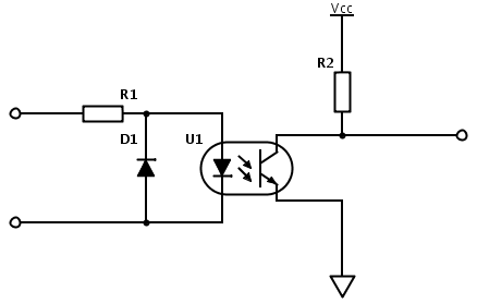
I am trying to provide zero crossing detection to my controller. Using the schematic below, I managed to generate square wave signal, representing positive v/s negative half-period. The problem is that the resistor needs to be quite large :
CTR > 10% Max diode current: 60ma. I choose 30 ma working diode current. This yields 30ma * 230V = 6,9W for R1.

Quite the heater. Also, voltage rating above 400V is required. I realize that a transformer could be used to step down the mains voltage. However, those guys tend to be bulky and rather expensive. Any recomendations?

Edit:
I found some nice explanations onHardware deign and noise suppression on the site. stevenvh's answer looks especially promising on calculating the resistor value. So let's keep my question more general. What are the approaches - resistor, transformer, others. What characteristics are desired in the optocoupler? Is the chosen driving current (30mA) huge and unnecessary?
enter image description here

\$\endgroup\$

2 Answers 2

6
\$\begingroup\$
  1. Consider replacing the optocoupler chosen, with one that is designed for direct interface to a mains power line. For example, Fairchild Semiconductors MID400 is one such part.
  2. Use a much lower LED current. While your opto may specify a fairly large (20mA to 100 mA, even 1 A in some cases) drive current for the LED, many will work fine at as little as 1 to 2 mA: The part's transfer curve should provide enough information to confirm this.
  3. A capacitor can be used as an impedance element for dropping the input AC voltage, instead of the resistor. As the voltage drop is almost entirely pure reactive, there is hardly any thermal dissipation to be concerned about. You do however require "X" rating capacitors, designed for use in AC mains circuits.
\$\endgroup\$
6
  • 3
    \$\begingroup\$ For 3.: and you must take the phase shifting into account! After all, this circuit is about detecting the zero-crossing moment. \$\endgroup\$ Commented Mar 10, 2013 at 9:25
  • \$\begingroup\$ The optocoupler that I have on hand is an 4N27 - and they advertise it as suitable for "AC Mains Detection". In the datasheet, the test circuit uses 10ma diode current... \$\endgroup\$
    – Vorac
    Commented Mar 10, 2013 at 9:40
  • \$\begingroup\$ @WoutervanOoijen Given a possible 1.x Volt diode drop v/s a 108.x to 218.x Volt capacitor drop, the phase shift ought to be nominal, wouldn't it? Speculating here, not basing my comment on any calculations. \$\endgroup\$ Commented Mar 10, 2013 at 12:37
  • 1
    \$\begingroup\$ Reducing the current worked just fine! jippie's answer is also excellent, but would be more relevant in an earlier phase of the project - the design of the architecture. Using a whole wall adapter for zero crossing, without powering something with it seems such a waste of resources. \$\endgroup\$
    – Vorac
    Commented Sep 12, 2013 at 9:46
  • 2
    \$\begingroup\$ @AnindoGhosh actually, the phase shift is 90, as the current through a capacitor is at 90 degrees to the voltage phase. This can be seen here tinyurl.com/yc4drqmn \$\endgroup\$
    – BeB00
    Commented Jun 29, 2017 at 6:06
4
\$\begingroup\$

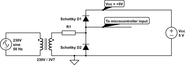
I'm personally planning to make a zero crossing detector using an old power adapter, one with a conventional transformer. This ensures absolute safety to the circuit. I plan to feed the low voltage output through couple of resistors and clipping diodes to a microcontroller and won't need a optocoupler.

For my application however the exact zero crossing isn't too critical as long as relative timing is stable. When using a transformer Wouter's comment about the phase shift will probably apply too. Notice that the circuit diagram below is not for supplying Vcc to the microcontroller. Vcc as marked in the diagram is the power supply already present for powering the rest of the circuit. It is here only used to clamp to.

schematic

simulate this circuit – Schematic created using CircuitLab

\$\endgroup\$

Your Answer

By clicking “Post Your Answer”, you agree to our terms of service and acknowledge you have read our privacy policy.

Not the answer you're looking for? Browse other questions tagged or ask your own question.