13
\$\begingroup\$

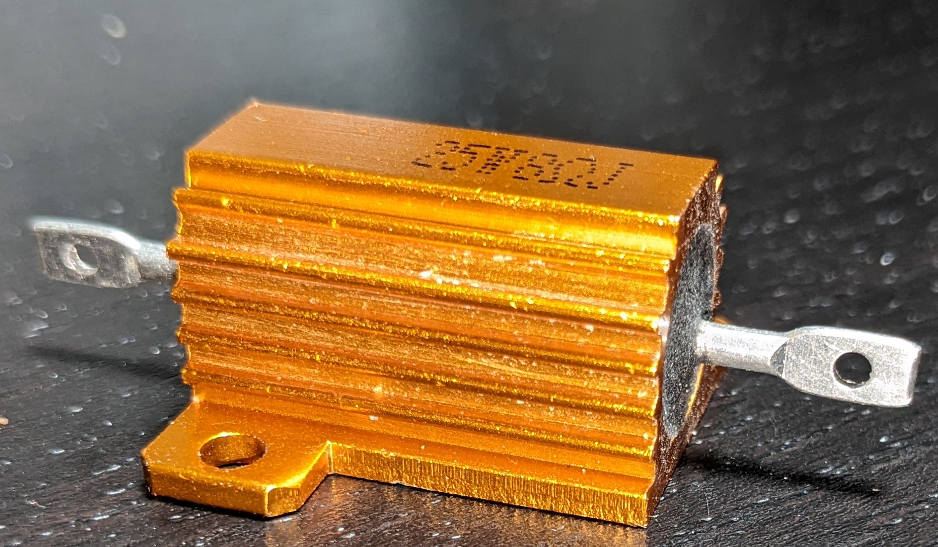
Why do the leads of some resistors have holes?

Is it to:

  • Run a wire through it before soldering? If so, what is the best technique?
  • Run a tiny screw through it for connecting a tiny lug?
  • Provide a barrier against conductive heat transfer between the body and the tip (by both the hole and the flattening, soldering the tip only)?

Example (the undeformed part of lead diameter is 2.5mm in his case; the hole diameter is 1.8mm): resistor
\$\endgroup\$

5 Answers 5

29
\$\begingroup\$

It's called a solder lug terminal. Or a pierced terminal.

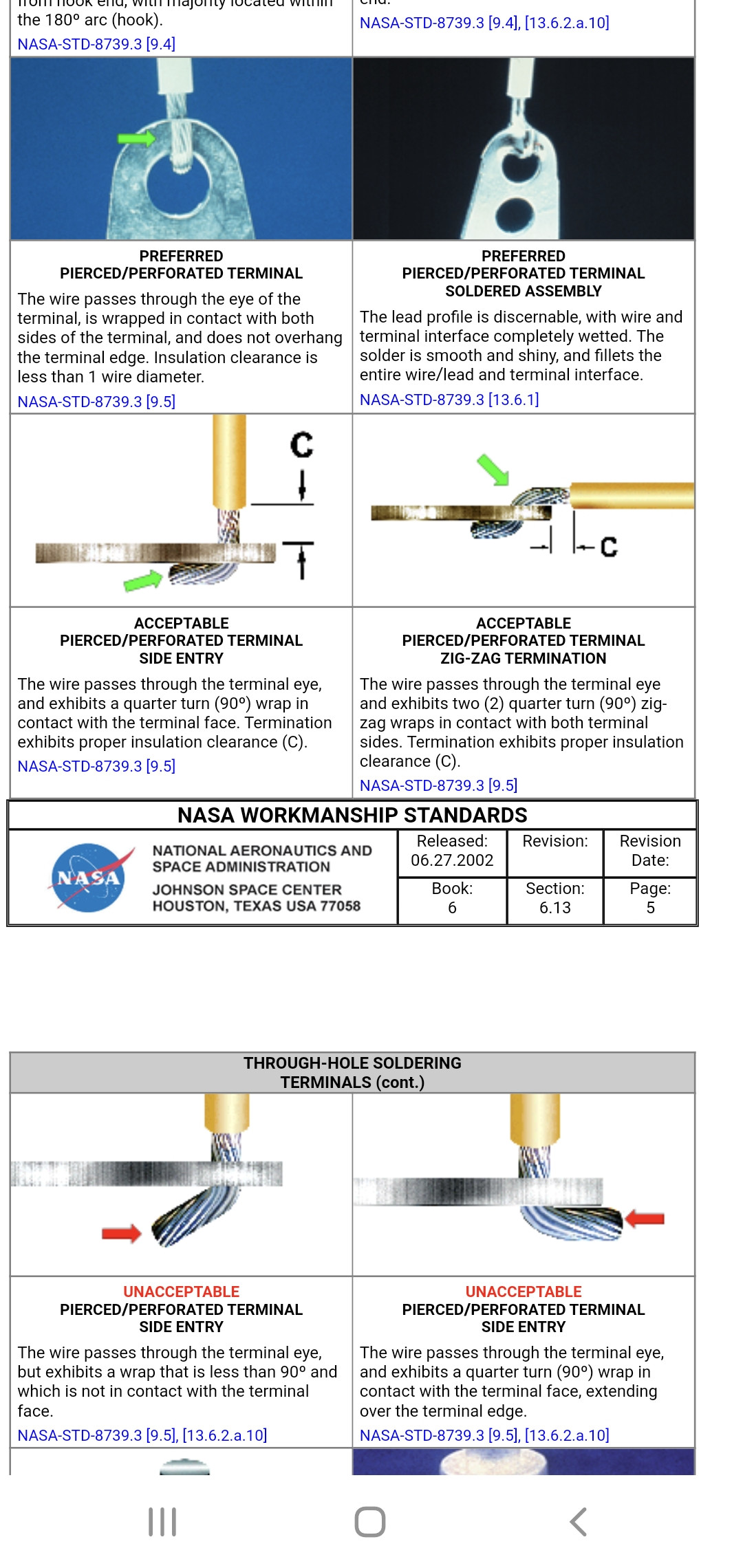
You want to use a short j hook, a 90 degree bend, or a zig-zag z hook depending on your application and solder it.

enter image description here

https://workmanship.nasa.gov/lib/insp/2%20books/links/sections/613%20Terminals.html

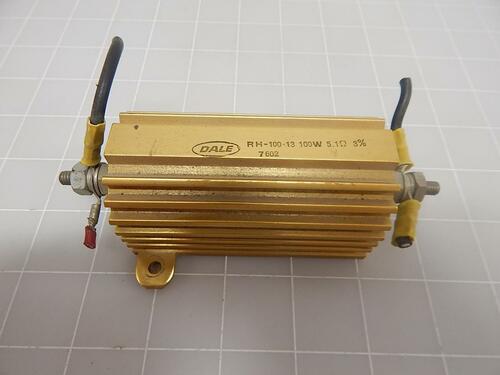
It is not made for a screw lug, the same model high wattage resistors do come with threaded nut and bolt variations for lugs instead. These tend to be 50 to 100 watts or higher models, off the shelf anyway.

enter image description here https://cdn11.bigcommerce.com/s-h1jjeo/products/67092/images/306727/T66974%252520%25282%2529__26242.1438139758.500.750.jpg?c=2

Yes you could use a tiny nut and bolt (not a screw!). That's not the intended application but it will work if you use precaution. Make sure it's tight and use threadlocker. Vibration and thermal cycling could cause it to unscrew.

And the size and shape is for convenience of attaching a properly sized wire. At 25 Watts 8 ohms 3 amps, you are not connecting a thin little 22awg wire where a bare lead is enough.

\$\endgroup\$
11
\$\begingroup\$

As the others have said, the purpose of this termination is to solder a wire.

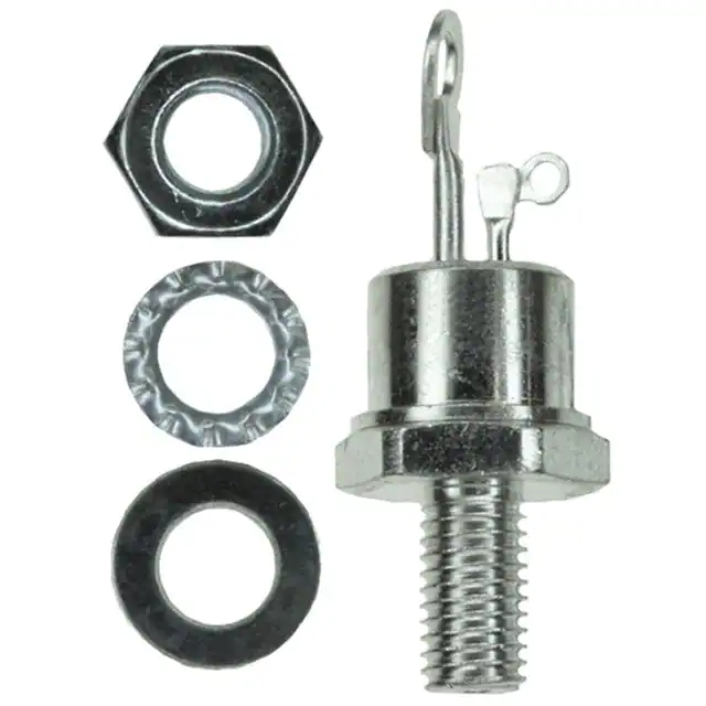
It's common on components that can't fit on a PCB because they're supposed to fit on a chassis or be screwed on a heat sink. So they have to be connected to the main PCB with wires. Here's a thyristor:

enter image description here

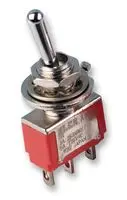
And here's a switch with the same kind of terminals:

enter image description here

They're all the same, stick a wire through the hole, secure it by bending or twisting, and solder. Heat shrink is a plus.

Assembly is quite labor intensive and can't be done with a pick and place machine, so these are less popular these days.

\$\endgroup\$
0
7
\$\begingroup\$

Used so that a wire can be looped through the hole which can make it easier for soldering.

Some will go through the hole then twist the wire round itself several times, others will just go through the hole and bend the wire so it self-clamps then trim off excess - up to you.

\$\endgroup\$
6
\$\begingroup\$

It's to pass a wire through and crimp it back on itself before soldering. You can put fiberglass or shrink sleeving on there for insulation (fiberglass if you expect it to run really hot).

\$\endgroup\$
2
\$\begingroup\$

It's for soldering. NASA calls those a "pierced terminal" and has a special document for what their standards are for soldering to them.

Section 9.5 Pierced Terminals

See: https://nepp.nasa.gov/docuploads/06AA01BA-FC7E-4094-AE829CE371A7B05D/NASA-STD-8739.3.pdf

Alternatively: NASA-STD-8739.3 "NASA Training Program Student Workbook for Hand Soldering" Procedure 4 "Pierced Terminals"

https://protostack.com.au/download/NASA%20Student%20Handbook%20for%20Hand%20Soldering.pdf

\$\endgroup\$

Your Answer

By clicking “Post Your Answer”, you agree to our terms of service and acknowledge you have read our privacy policy.

Not the answer you're looking for? Browse other questions tagged or ask your own question.