3
\$\begingroup\$

Why is it that impedance matching does not matter if the transmission line is shorter than the wavelenght of the signal?

Why do you get zero reflection if the line is shorter than the wavelenght?

Also, does this mean you do not need impedance matching for DC lines (as the wavelenght is "infinite" for DC)?

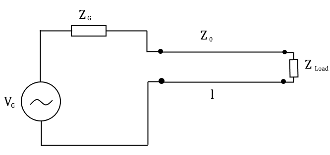
enter image description here

Also, here is my understanding of why there is a reflected wave: When we have a line impedance \$Z_0\$ energy is stored (reactance, \$X\$) in the wires or realised (resistance, \$R\$). This makes a current go through the wire. If \$Z_{Load} \neq Z_0\$ then the current flowing through the load will be different from the current flowing through the wire. The remaining current that does not flow through the load gets reflected. Is this correct?

\$\endgroup\$
2
  • \$\begingroup\$ You try a TL line on Falstad Circuit Simulator. It has a nice animated visualization. \$\endgroup\$
    – ee_student
    Commented Aug 10, 2022 at 14:48
  • 1
    \$\begingroup\$ Note that when one does not use the "line transmission" model, one should use the "lumped" model. \$\endgroup\$
    – Antonio51
    Commented Aug 10, 2022 at 15:44

5 Answers 5

2
\$\begingroup\$

EE&O.
What is a "short line"?
Here, length "line" used = 1 m -> 5 ns -> lambda in cable = 1 m -> f = 200 MHz.
Zo = 50 Ohm. C=101 pF/m. (RG52) -> parameters "lumped" circuit.

A "short line" is used when results between the "ideal line" and "lumped" circuit (one block) are "identical", with a little margin error.

One can make this comparison easily. For one configuration only (Load = 50 Ohm).
See these pictures. One is for "amplitude", the other is for "phase" comparison.
Chose your error "budget" -> read until what usable frequency.

Amplitude comparison, if 1 dB is ok, then fmax = ~ 30 MHz. enter image description here

Phase comparison, if 5° is ok, then fmax = ~ 25 MHz. enter image description here

\$\endgroup\$
3
\$\begingroup\$

Why is it that impedance matching does not matter if the transmission line is shorter than the wavelength of the signal?

The golden rule we use is if the transmission line is shorter than one-tenth of the shortest significant wavelength of the signal, we can ignore the effects. However, you do get reflections but they are so short-lived (usually) that they pose no problems (on most circuits).

Why do you get zero reflection if the line is shorter than the wavelength?

If the line is not correctly terminated you do get reflections. I can't understand where your statement came from but, it is incorrect (other than the case of a line that is perfectly terminated).

does this mean you do not need impedance matching for DC lines

To extract maximum power from a source that has a DC impedance (aka resistance) you need to impedance match.

Also, here is my understanding of why there is a reflected wave:<...> Is this correct?

I'll stop you right there and say no, that isn't correct and, you should go and google the telegrapher's equations - it's significantly more complex (and mathematical) than you envisage and, whole chapters in books are written about it.

But, I have made answers here and here about how ohm's law appears to be violated and, in order to "make things good", a reflection occurs.

\$\endgroup\$
0
2
\$\begingroup\$

This is a great question and is a tricky set of fundamentals. There is some good info in the other answers, I’ll provide another perspective here.

Your question isn’t confined enough to provide a direct, concise answer.

For example, what is “short”? It depends. 1/10 wavelength is a common rule of thumb. But if your source is a model of a power amplifier, then a large mismatch is bad no matter what the line length. If it’s a SERDES channel, then the length of the line relative to the unit interval of the data stream matters. Or, the time that equalizer taps can compensate for reflections might be most important. Or the amount of reflection matters in its impact on SNR but maybe the length matters less. It comes down to understanding the impacts of mismatch and the timing of reflections on the system. I’ve worked in systems where 1/10 wavelength is far too long, others it’s short enough to ignore.

Your circuit could be a 1/4 wave transformer which requires the line to be close to 1/4 wavelength.

In general, if the line length is short enough that expected reflection magnitudes don’t have a meaningful impact on the circuit in question, then it’s “short”. That’s usually somewhere around 1/10-1/20 lambda.

In your circuit, try calculating power to the load while varying Zg, Zo, Zl and see what the impacts are. That’s one metric. Then try calculating the standing wave ratio, which will tell you what maximum voltage will be presented back to the source, to see what happens. A power amplifier likes a good match, maybe 2:1 or 3:1 VSWR, how much mismatch does this require, and what impact does length have?

\$\endgroup\$
2
\$\begingroup\$

Why do you get zero reflection if the line is shorter than the wavelength?

You always get reflection in a mismatched transmission line -- it's just that for a short transmission line you can sometimes safely ignore the effect, or you can treat it as a lumped element. The shorter the transmission line is (in wavelengths), the more likely this is.

Why is it that impedance matching does not matter if the transmission line is shorter than the wavelenght of the signal?

Consider a couple of wires twisted together, about 1 inch long. It's a transmission line of 100 ohms or so, that's -- well -- an inch long. Depending on the insulation and the degree of twist, it's maybe two inches long, electrically, and it's got an impedance somewhere between tens of ohms or 150 ohms or so.

If you use that twisted pair of wires as a component with the end left open, then:

  • At DC it'll act like an open circuit -- you can completely ignore transmission line effects.
  • At frequencies such that it's less than 1/100 or so of a wavelength long (so, around 100MHz), it'll act like a capacitor. It'll be close enough for most purposes up to 1/10 of a wavelength (1GHz). If you know the velocity factor, length, and characteristic impedance you can calculate the effective capacitance using transmission line equations, but you won't see that effective capacitance changing.
  • At a frequency where it's 1/4 an electrical wavelength long (2.5GHz), it'll look like a dead short -- zero ohms, no capacitance effect at all. That's shorter than your one wavelength, but boy, does it matter.
  • Between 1/4 and 1/2 wavelength long, it'll look like an inductance.
  • Etc.

Also, does this mean you do not need impedance matching for DC lines (as the wavelenght is "infinite" for DC)?

"Pure" DC doesn't exist, and cannot in this finite-duration universe. Usually for close-to-DC lines you can ignore transmission line effects -- but if you have fast transients on the line, then it'll bounce off of impedance discontinuities, and then you have to care.

\$\endgroup\$
1
\$\begingroup\$

I did some research on this a few months ago. Let's say you have a DC source of 3V, and a load of 200 ohm. The characteristic impedance of the line 50 ohm.

  1. At time zero, the source sees an impedance of 50ohm, so current is 3 / 50 into the TL.

  2. Some time later, voltage 3, current (3 / 50) will reach end of transmission line and see a load of 200.

  3. At that point current can do two things:

A. Sink in whole or in part into 200 ohm resistor.

B. Return back along transmission line. In B, it has 2 further options:

B.1. return in the same voltage as the incident wave

B.2. return in the opposite voltage (negative in this case) amplitude.

If anything returns, the amount of returning current adds or subtructs from the voltage of the incident wave at the end of TL line.

It solves the following equation (X is a fraction between 0 and 1):

3V + X * (3/50)A * 50 = (1 - X) * (3/50)A * 20Ohm

For case B.2.:

3V - X * (3/50)A * 50 = (1 - X) * (3/50)A * 200 Ohm.

In having too much current to sink into the 200 ohm resistor, it chooses to increase the voltage at the end of the TL line (when the incident wave gets there). The original current is distributed between 200 ohm resistor and a backward wave that adds to the voltage of the incident wave:

3V + voltage of backward wave = 3V + (backward travelling current) * 50 ohm = voltage across 200 ohm resistor = current across 200 ohm resistor * (200 ohm)

If the 200 ohm resistor were smaller than 50, it'd be the other way around (Case 2.B.), and the backward traveling wave will be of negative voltage and reduce the amplitude of 3V to (3V - (backward travelling current) * 50ohm).

If the load is 50 ohm, there won't be backward travelling wave (fraction X would be zero).

The backward travelling wave will reach the source at the same delay it took the incident wave to reach the load.

Meanwhile, the 3V will continue producing incident waves on its end (travelling through the line towards the load at a constant speed).

The backward wave will travel on top of incident waves (waves can travel over each other).

When it reaches the source, it will solve:

Let's say the backward voltage was 2V (current 2V / 50). You can solve the equation to know exactly.

3V DC source = 2V (backward wave) + (fraction of (2V / 50) current reversing to forward wave) * 50 Ohm

Some current reverses again into an incident wave to make the voltage at the start of the transmission line 3V as is the voltage of the DC source, and the rest of the current sinks into the 3V DC source (the current that doesn't reverse from backward wave back to forward wave).

(Since this solution encompasses the DC source and the backward wave, this is the complete solution for the start, or left edge, of the TL line for the moment the backwards wave comes back. There is nothing to add by superposition to the start of the TL line at that moment. Of course at the same moment some incident wave from earlier will reach the right end of the TL line, and will require a separate solution for the right end of the TL line).

(When there's no backward wave, the 3V at the start of the TL is achieved by an incident wave of (3V / 50 ohm) current into the TL line).

This is how a circuit simulator can track a lossless TL line, without using R, L, C as a model. There are general equations for AC sources, but it's nice to understand how to solve moment by moment (like in AC there are phasor equations, but it's nice to know the specific solution at each timestamp).

You could try it in LTSpice and in the Falstad simulator..

If you track this process for a DC source, with a TL line with, say, 500ns delay, you'll see that the effects of the mismatch hardly amount to anything except at the very beginning.

(This is not so difficult when it's explained, but seems like most books don't bother explaining those mechanics, and jump to generalizations instead).

If you have Z source (Zg in your figure), the initial incident wave will be: 3V / (Zg + 50). In my answer, I assumed that you don't have Zg, but the process is the same regardless of Zg, or, for that matter, the kind of circuit stage you have before and after the TL line.

\$\endgroup\$

Your Answer

By clicking “Post Your Answer”, you agree to our terms of service and acknowledge you have read our privacy policy.

Not the answer you're looking for? Browse other questions tagged or ask your own question.