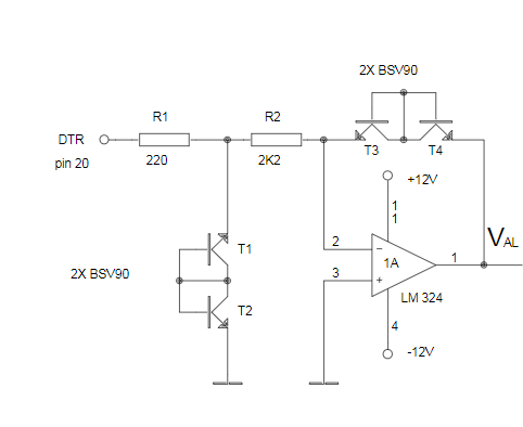
This picture is part of a circuit designed to measure capacitance. The control circuit would apply +12V or -12V on "DTR pin 20" and the two resistors give a minimum and maximum voltage reference which is used to compare with the charging/discharging capacitor's voltage.
The book says T1 & T2 are used to ensure a stable voltage drop on R2, which in turn ensures a constant current flow through the base-emitter junctions of T3 & T4. It specifically asks for BSV90 transistors which I've found out that are for high speed applications.
I can't figure out how current is supposed to flow through those transistor pairs, nor how T1 & T2 are supposed to stabilize the voltage across R2. I also don't know what the point of T3 & T4 are considering 1A is supposed to be a sort of voltage follower to ensure the +12V or -12V going towards the capacitor.

