1
\$\begingroup\$

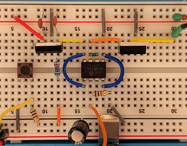
I've created a circuit using a gate driver IC, TC4420, which allows me to dim a 24 V LED strip using 20 kHz PWM from an Arduino UNO. I got some help the other day and attempted to make a small scale prototype on the breadboard. A gate driver seemed more approachable than discrete components but I'm getting results I can't understand.

The dimming sequences in the circuit below are not pulling the LEDs fully off. I can't run VDD to the high side of the LEDs because of the 24V source, but I thought this would work. I'm new to using my oscilloscope but it looks like the power side of the PWM is only going from 0 to 10 V. The only time I see 24 V is rail to rail or I see +10/-14 PWM when measuring from gate to drain.

One additional aspect I haven't been able to grasp is how to handle the voltage at the gate. Even if I get a gate driver that will work at 24V, so many MOSFETs seem to have 20Vgs limits I feel like I'd be in the same spot. Is the answer here really to find a MOSFET with >24Vgs? I think I just don't quite know what I'm doing.
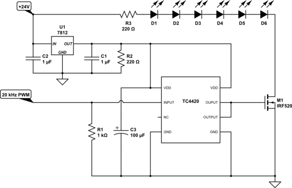
schematic

simulate this circuit – Schematic created using CircuitLab

breadboard

\$\endgroup\$
5
  • \$\begingroup\$ Why not simply drive the gate of the MOSFET and leave the driver out? It is an inverting driver. \$\endgroup\$
    – Gil
    Commented Feb 14, 2023 at 2:26
  • \$\begingroup\$ I think the TC4429 is inverting and not the TC4420, unless I've made a mistake. As to why I'm driving it; 5 V from a logic pin isn't enough to fully open the gates on many power drivers and I need decently fast switching speeds for 20 kHz 8 bit PWM. \$\endgroup\$
    – eemoob
    Commented Feb 14, 2023 at 2:30
  • 2
    \$\begingroup\$ Your MOSFET has a 4V threshold and should work. Hopefully if the PWM is at least 6 volts. It is not the gate drain limit you should worry about, the gate is isolated from the drain, there is only capacitive coupling. Vgs is Source gate voltage. The reason it is going from 0 to 10V is probably because of the diode leakage. Try placing a single 10K resistor across all of the diodes, that should allow them to turn off. What happens if you place the PWM input to the gate and ground? You may want to put a few hundred ohms in the gate lead. Also be sure the gate is going to zero. \$\endgroup\$
    – Gil
    Commented Feb 14, 2023 at 2:46
  • 1
    \$\begingroup\$ looks like the power side of the PWM is only going from 0 to 10 V using a "megaohm" probe+scope input from GND to power-FET drain? At \$V_{GS}\$  0, the MOSFET will allow tens of μA depending on type & temperature. Try measuring the voltage across R3 - you can compute the current. Or disconnect the drain and measure the voltages at drain and "lower side of LEDs" separately. \$\endgroup\$
    – greybeard
    Commented Feb 14, 2023 at 10:46
  • \$\begingroup\$ Thanks all! My problem is not in the circuit but I lacked the experience to find it right away. For some reason my atmega328p-pu is still sending a small signal at "0" duty cycle so the problem seems to be in the PWM. Your suggestions helped me get this far. \$\endgroup\$
    – eemoob
    Commented Feb 14, 2023 at 13:38

0

Your Answer

By clicking “Post Your Answer”, you agree to our terms of service and acknowledge you have read our privacy policy.

Browse other questions tagged or ask your own question.