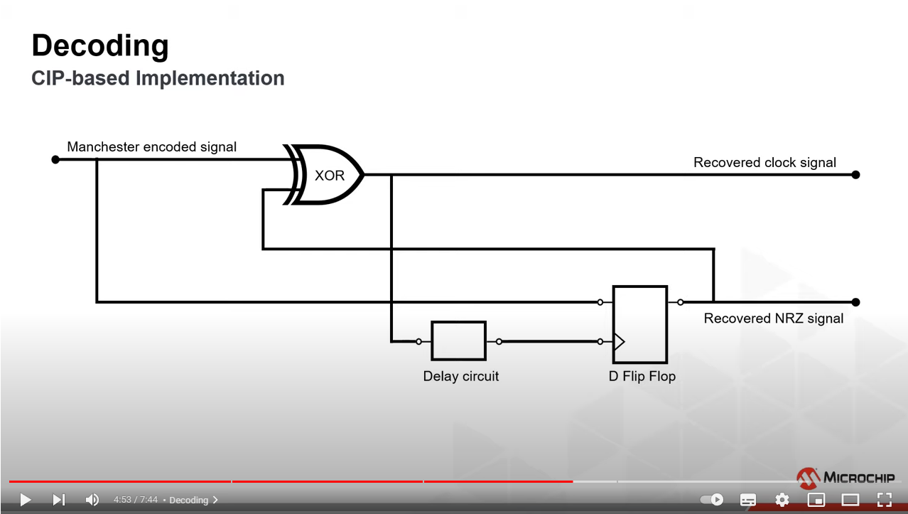
This video describes a decoder circuit for Manchester encoded signals, and the same circuit is also mentioned in this article. I can understand the circuit, and I'm interested in what different approaches exist for creating the delay in the delay circuit (should delay the clock to D flip flop by 1/4th period, since that always samples the correct non-return-to-zero value. ) I also note that the NRZ is shifted 1/4th of a period, but the XOR to recover the clock rate still works, the rising edge is still synchronized, it just has occasional clock pulses with a different duty cycle. The delay circuit delays the clock by 3/4ths of a period (to sample 1/4th period too early. ) How is that achieved, usually?
I've simulated the circuit in VHDL, with a delay circuit that already knows the clock rate, and then it works. But that is kind of meaningless because the point of Manchester is to recover the clock without knowing it. I was curious to if there are solutions where the clock is delayed 3/4ths of a clock signal using only the clock signal in the Manchester encoded signal. Or as close to that as possible. And if such solutions can adapt dynamically to different frequencies.
library IEEE;
use IEEE.STD_LOGIC_1164.ALL;

entity decoder is
    Port ( clk    : in STD_LOGIC;
           mcr_enc: in STD_LOGIC;
           clk_rec: out STD_LOGIC;
           NRZ_rec: out STD_LOGIC
           );
end decoder;

architecture Behavioral of decoder is

signal NRZ : STD_LOGIC := '0';
signal REC_CLK : STD_LOGIC := '0';
signal clk_rec_buf: STD_LOGIC_VECTOR (7 downto 0)  := "11101111";

begin
    NRZ_rec <= NRZ;
    clk_rec <= REC_CLK;
    REC_CLK <= mcr_enc XOR NRZ;
    process (clk)
    begin
        if rising_edge (clk) then
            if clk_rec_buf(5) = '0' and clk_rec_buf(4) = '1' then
                NRZ <= mcr_enc;
            end if;
            clk_rec_buf <= clk_rec_buf(6 downto 0)&REC_CLK;
        end if;
    end process;
end Behavioral;
This is a pretty broad question. I'm very interested, if anyone is interested in explaining the answer to me and understands what I ask and why.

