3
\$\begingroup\$

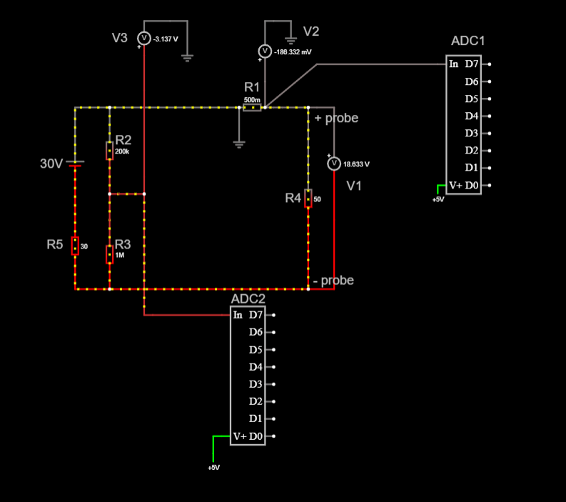
I am implementing digital voltage and current measurement on an old power supply.

Due to the design of the supply, I am forced to use the positive output probe as a common ground for my ADC and MCU.

However, this means that both the voltages on R1 (0 to 0.5 V) and R2 (0 to 5 V) will be negative (as measured by V2 and V3) in reference to ADC and MCU, which I need to convert to positive for ADC measurement.

power supply voltage and curent measurement

I can't use an op-amp inverter, because load resistance will be variable, which makes fixed unity gain impossible.

I don't really have any other ideas.

What would you do in my place?

\$\endgroup\$
1
  • \$\begingroup\$ link to the circuit: link \$\endgroup\$
    – Atropin
    Commented Feb 10 at 16:23

3 Answers 3

4
\$\begingroup\$

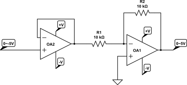
You can use two op-amps, the first as a unity gain voltage follower to buffer the negative voltage (looks like you might have a -18V supply available) and the second as the inverter.

That's my suggested topology to solve the problem.

Details such as exact resistor values and op-amp selection depend on the accuracy level required, supply rails available and so on. Don't expect to get exactly to +5V with a 5V supply, even if you use a "Rail-to-rail IO" op-amp. There are some (few and a bit $) high-voltage RRIO op-amps.

schematic

simulate this circuit – Schematic created using CircuitLab

\$\endgroup\$
3
  • \$\begingroup\$ Do I feed the output from the buffer to the second amplifier? What will be the feedback at the second amplifier? \$\endgroup\$
    – Atropin
    Commented Feb 10 at 16:48
  • \$\begingroup\$ See the above edit, but remember the devil is in the details- how close you can get to the rails on both inputs and outputs, and what happens if the op-amp output to the ADC goes outside the rails. \$\endgroup\$ Commented Feb 10 at 16:54
  • 1
    \$\begingroup\$ This works, thanks a lot. You're right that I can't get to 5V, I will just scale down the voltage divider so that maximum measured voltage will be 2.5 V instead of 5 V. \$\endgroup\$
    – Atropin
    Commented Feb 10 at 17:40
2
\$\begingroup\$

I am implementing digital voltage and current measurement on an old power supply.

Simpler approach: Take two 5-digit digital voltage displays you can get on eBay, Amazon, etc. They have an STM08 MCU you could reprogram if you wish, but they generally do the job fine as-is.

Their ADC inputs are differential, you just need to modify the display a little bit (cut a trace). The ADC common mode range is within the supply rails, so there's plenty of "play". The input to the ADC is scaled with resistors, so for current shunts you can change the resistors to have a small shunt voltage display as-if it was in the volts range.

I bet you could have the displays up and running in an afternoon that way.

Here are the details of the modification needed for the display to make it run from 3V-5V directly, and have differential (floating) ADC inputs. That's from a simple little project of mine I've done as a demo of how simple some instrumentation can be.

I was first exposed to those 5-digit readouts in IMSAI Guy's videos (not sure which one).

NFM has a nice video explaining the upgrade process that may be of interest to you.

For details about those voltmeters see:

https://www.eevblog.com/forum/projects/$5-voltmeter-with-5-digit-(0-1mv)-resolution/150/

https://eddy-em.livejournal.com/73375.html

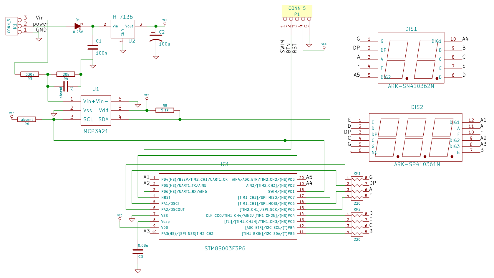
From the latter, here's the schematic of the module:

enter image description here

Newer versions of the module use a single 5-position display instead of a 2+3 split.

\$\endgroup\$
2
  • \$\begingroup\$ You might haved just saved me from a ton of headache :D \$\endgroup\$
    – Atropin
    Commented Feb 10 at 19:32
  • \$\begingroup\$ @Atropin The idea comes from IMSAI guy. There's a video from NFM where the same meters are used for a similar upgrade, I imagine, to your plans. It is still worth it IMHO to "free up" the negative end of the ADC differential input from ground. I haven't watched the NFM video to check if that was done there too. I updated the answer with more details from my notes. \$\endgroup\$ Commented Feb 11 at 1:16
0
\$\begingroup\$

I can't use an op-amp inverter, because load resistance will be variable, which makes fixed unity gain impossible.

But you can, and you don't need to worry about "fixed unity gain". You can use one (1) inverting op-amp per signal:-
a) one to sense the voltage, and
b) one to sense the current.

In fact, the situation you have here is perfect for op-amps - and you won't need a negative power supply, you can use the same supply as for the ADC & MCU (+5V); provided you keep the output of the op-amps below 5V.

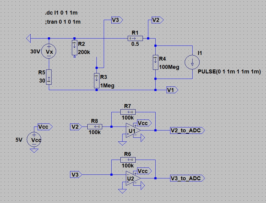
The schematic below shows the idea. Consider V2, which is the voltage of the shunt resistor, R1. When your "old power supply" Vx is supplying 30V to the load, this voltage will be negative wrt GND, and will be scaled at 0.5V per amp of load current (Since R1 is a 0.5ohm resistor). This is easily converted to a positive voltage by an inverting op-amp, U1, and then scaled by the ratio R7 / R8 - in this case, the scale is 1, so 1A of load gives V2=-0.5V which is converted to +0.5V by U1. You could make R7=200k ie: twice R8, so that the scale factor is 1A per volt, ie: 1V at U1 output represents 1A of load current. Adjust R7 and R8 to suit your particular requirements, just be sure to keep the value of R8 much higher than the value of shunt resistor R1 (so that the current in R8 is negligible and does not adversely affect the accuracy).
enter image description here

Now consider V3, which is the voltage of the output of the power supply. We can remove R2 (200k) from the circuit, and connect R3 directly to U2's negative input. R6 converts the current flowing in R3 to a positive voltage that is proportional to the current in R6. Since the negative input of U2 is a "virtual earth" (so is the negative input of U1 for that matter), then the current in R3 is directly proportional to the voltage at V1. At 30V, R3 current is 30uA. This current flows in R6, which then sets the voltage at the output of U2. At 30uA, the voltage across R6 will be 3.0V, meaning that U2 output is one-tenth of V1.

The simulation result (below) shows what happens when load current (current source I1) is swept from 0A to 1A. The horizontal axis is load current (current through R1).
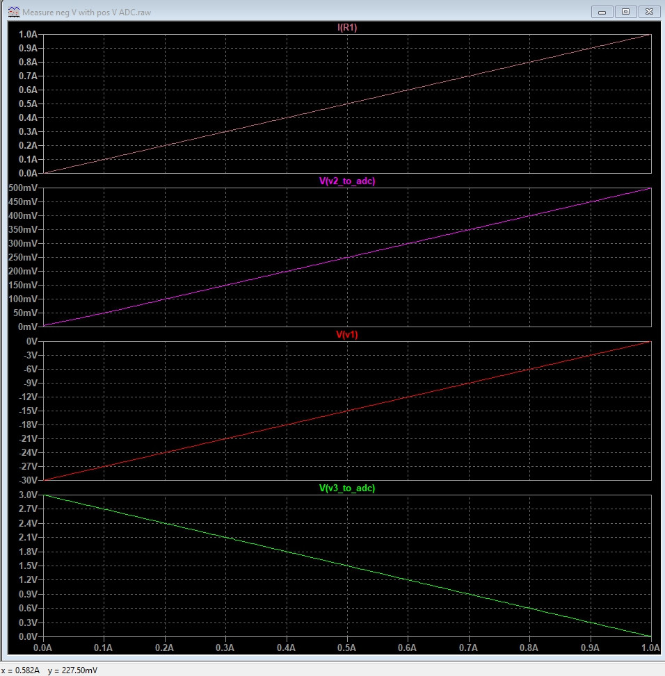
enter image description here

\$\endgroup\$

Your Answer

By clicking “Post Your Answer”, you agree to our terms of service and acknowledge you have read our privacy policy.

Not the answer you're looking for? Browse other questions tagged or ask your own question.