I’m building a project which displays the total volume of water which has passed through a pipe. I want to use an ultrasonic flow transducer https://www.digikey.com.au/en/products/detail/audiowell-international-llc/US0014-001/8628602 . Note that for this project I cannot disturb the waterways at all. I have two of them in order to perform the calculation. I’m unsure how to wire up the transducer and what kind of data I will receive. The data sheet is also not clear as to this. I’d love to hear any thoughts on this. Thanks again.
-
\$\begingroup\$ bronkhorst.com/int/service-support-1/technologies/… \$\endgroup\$– Antonio51Commented Mar 14 at 15:57
-
\$\begingroup\$ You could buy an off the shelf solution or you could design your own, if you are trying to do this yourself you could spend many months developing this as it's a complex tech and usually on a senior project level at a university. Either way this question is off topic and needs an update to make the question more specific. If you have a question on how to amplifiy the sensors or design a circuit, we can help with that, the flow sensor measurement is a fluid mechanical design problem \$\endgroup\$– Voltage Spike ♦Commented Mar 14 at 19:46
-
\$\begingroup\$ Yes I would be targeting how to design the circuits and read the sensor. The fluid mechanics once the data is being read should be okay to work through. The idea is to build as lower cost as possible water flow meter without having anything interfere with the water way in the pipes. Thanks again for your answer. \$\endgroup\$– JoeblogsCommented Mar 15 at 2:02
4 Answers
From the datasheet:
The ultrasonic flow sensor is used as the core element of ultrasonic flow meters.
What you've bought are two components to be used in building a flow meter. You have to design the housing, driving circuit and receiver circuit.
Have a look at their evaluation kits page and see the complexity you're up against. I think you've underestimated the amount of work you'll have to do to create your meter.
A further problem is that this will give you a flow rate which you would have to integrate over time to get a volume.
A simpler solution would be to look for an impeller type of flow sensor. These typically have a magnet on the impeller and a reed switch outside. You just count the pulses and multiply by the volume per pulse.
-
2\$\begingroup\$ Two transducers (even once built into a full system) only give the average flow rate along the line between the two transducers. If you were to integrate over the whole cross-section, the calculated volume can be wildly out at higher rates due to the flow rate being lower near the edges. You end up needing multiple transducer pairs with different paths through the pipe to measure the velocity profile within the pipe before integrating. \$\endgroup\$ Commented Mar 14 at 11:07
-
\$\begingroup\$ Okay interesting thanks for your feedback. The difficulty is that for the project we cannot impact the pipe. So any inline solution is prohibited (which I think the impeller would use?). Hence the ultrasonic flow meter was my thinking, and saving on cost by assembling independently. What are your thoughts? Thanks again \$\endgroup\$– JoeblogsCommented Mar 15 at 1:59
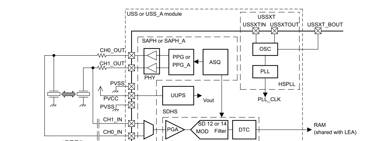
You could build a system with a TI MSP430FR6043 MCU or similar which contains almost all the circuitry required to build an ultrasonic flowmeter. They even provide some proprietary algorithms for measurement and the on-chip hardware reportedly delivers "±12.5-ps differential time of flight (dToF) accuracy at low to high flow rates and across operating temperature". Picoseconds are pretty small.
With most of the hard work done by TI, the rest is merely a matter of hardware, software/firmware, testing, coming with a calibration rig, verifying accuracy under expected conditions, and manufacturing/production testing and supporting the systems over the design life.
-
\$\begingroup\$ Amazing, this seems like a very viable option. I’d love to discuss further. The microcontroller looks like it is quite low price, which means overall the project will still keep to budget. \$\endgroup\$– JoeblogsCommented Mar 15 at 2:06
In addition to using Spehero's chip OP will have to deal with the problem of acoustic coupling to the pipe.
Buying the transducers is not the beginning of the end. It is only the beginning of the beginning.
The manufacturer characterized them using an Agilent 4294A Precision Impedance Analyzer.
Since these are simple transducer (speakers) you need to wire them up to circuitry generating and analyzing the signals converting it to the metric you require.
I suspect you will be better of with an more integrated solution Audiowell offers. eg: FS0001-000. These have UART M-bus output.

