3
\$\begingroup\$

I recently bought a DE0 FPGA board with GPIO headers.

The schematics shows that some of them are protected with BAT54S Schottky diodes. Does it mean that if I input 5v logic level they will be converted to 3.3V and protect the FPGA or do I need to step down the voltage by myself?
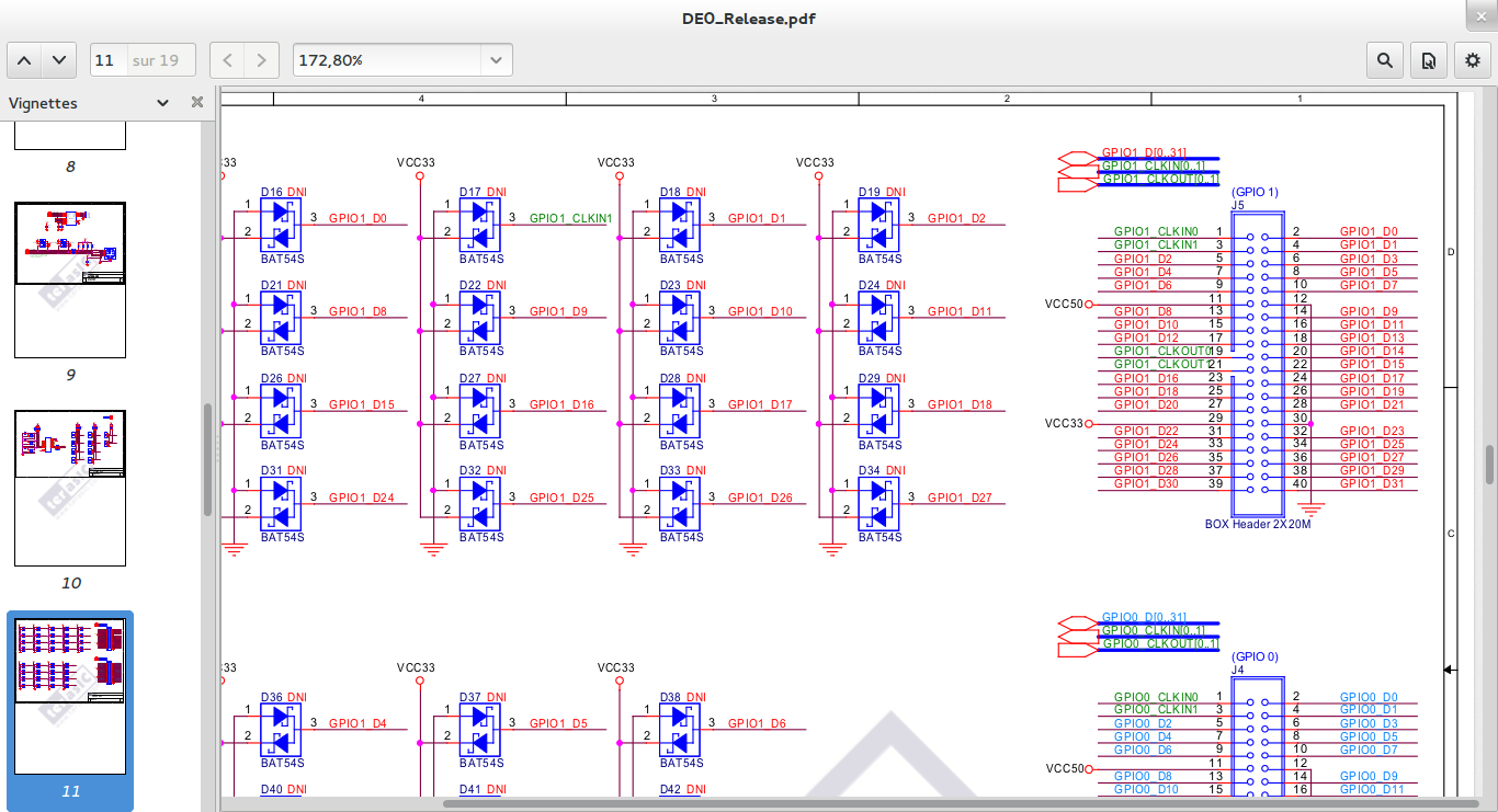
enter image description here

What is the easiest-safe way of converting 5v to 3.3v ?

\$\endgroup\$

4 Answers 4

0
\$\begingroup\$

Those diodes protect the pins from overvoltage, undervoltage, and electrostatic discharge. Basically, they prevent the voltage on the pin from crossing outside of the supply voltages, in this case above 3.3 or below 0.

If you want to feed in a 5v signal, put in a series resistor of maybe 100 to 1k ohms or so. The diode will clamp the voltage and the resistor will prevent too much current from being drawn from whatever is sourcing the signal. This only works for low speed signals. If you need something fast, then getting a dedicated level shifter chip is a better idea.

\$\endgroup\$
0
\$\begingroup\$

Those are clamp diodes. They prevent the voltage on the pin from going above Vcc+Vf or below GND-Vf. They do not perform level conversion, and they should not be used to do so since they usually can't take a lot of abuse.

The easiest way to perform level conversion is to use a IC such as TI's TXB01xx chips, but it is possible to use a MOSFET with some pullups for it.

\$\endgroup\$
0
\$\begingroup\$

Those diodes are more than likely for surge/ESD protection as oppose to "voltage level conversion" IF you were to connect 5V to one of these then yes they would be "clamped" via a diode to the 3v3 rail, but they would draw an increase in current from whatever is sourcing that pin

\$\endgroup\$
0
\$\begingroup\$

You asked

What is the easiest-safe way of converting 5v to 3.3v ?
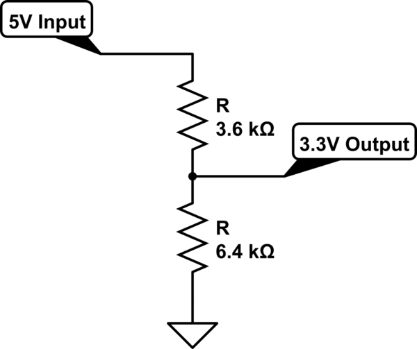
This seems to imply that you are using the GPIOs as input only. If so, you can get away with a voltage divider on each input pin:

schematic

simulate this circuit – Schematic created using CircuitLab

Assuming the load is high-impedance (>1Mohm), these resistor values should work fine.

\$\endgroup\$
2
  • \$\begingroup\$ Actually I will use both input and output, I am trying to read from ROM memory chips from a Gameboy cart. They require need Vcc = 5V but will (likely) see 3.3v as high input level for the address. I assume the ROM will output data as 5v high level. \$\endgroup\$
    – Romain B
    Commented Oct 31, 2013 at 17:52
  • \$\begingroup\$ I don't know if you have any bi-directional lines. If not, you can use the divider for inputs and either hope the ROM will accept your 3.3V logic outputs or else use a simple transistor stage (MOSFET or BJT and a couple of resistors) for the outputs to the ROM. Using a transistor will invert the signal but you can correct in software. \$\endgroup\$
    – DoxyLover
    Commented Oct 31, 2013 at 20:35

Your Answer

By clicking “Post Your Answer”, you agree to our terms of service and acknowledge you have read our privacy policy.

Not the answer you're looking for? Browse other questions tagged or ask your own question.