10
\$\begingroup\$

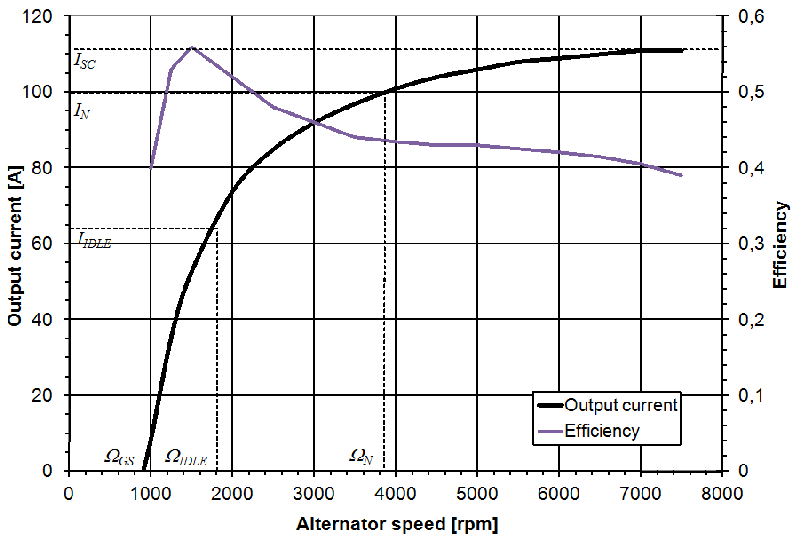
Automotive and some marine alternators typically have an efficiency curve with a peak of 60%.

alternator efficiency curve Image from http://www.intechopen.com

Alternators in other types of applications reach 96% of efficiency (excited rotor type.)

What are the factors that makes them so inefficient compared to other applications?

Is it pole-number, air-gap? Could the efficiency be improved with some modifications for stationary use or the unique way is maintaining the speed at the peak of efficiency?

UPDATE

@olinlathrop suggested some things, among that the environment the alternator works (temperature, vibrations, dust) means their robustness can be a trade off to the efficiency.

I agree in some points, although there's no objective answer, good sealed bearings would not decrease the efficiency that much, so I think temperature can be one of the factors as they are small and works near a combustion motor, even through having their own forced ventilation.

This is an alternator with a stated 80% efficiency at 450A and 28V. That's ~10KW.

The difference is that this alternator uses magnetics instead of electro-magnets in the rotor. Anyway, the ~95% efficiency alternator product sheet I read is a excited rotor one.

\$\endgroup\$
1
  • \$\begingroup\$ I converted this to a wiki question because no one has answered the efficiency question \$\endgroup\$
    – Voltage Spike
    Commented Mar 15, 2023 at 15:52

4 Answers 4

10
\$\begingroup\$

I don't design automobile alternators, so I can't say exactly what goes into the engineering decisions. However, here are some reasonable speculations.

Alternator efficiency is simply not a big deal in a car. The power the engine has to put out to move the car dwarfs what the alternator requires. If this tiny fraction of overall motor power were 1/3 less it wouldn't make much of a difference. Therefore efficiency can be traded away to get other more important parameters. Some of those probably include high reliability in a harsh environment, operation over a wide temperature range, and keep going while being splashed with water containing dirt and road salt and other crud. The volumes are very high, so keeping cost down must also be a major desire.

First, look at the cost of a 90% effecient generator of the same power compared to a car alternator. I expect it will be several times more. Then try operating the high-efficiency generator in a harsh environment like under the hood of a car and see how long it survives. Car alternators routinely survive this for 10-15 years. The high end efficient generator that cost several times more probably won't last a month in bad conditions.

It's all about what's really important and making the appropriate engineering tradeoffs in the design.

\$\endgroup\$
7
  • 1
    \$\begingroup\$ Another factor probably relates to what one must do to maintain a constant output voltage at differing speeds. Purpose-built engine-and-generator assemblies can be designed to run the engine at whatever speed works best for generation. Automotive alternators have to run at whatever engine speed makes the car travel with the desired velocity. \$\endgroup\$
    – supercat
    Commented Jan 10, 2014 at 21:51
  • 1
    \$\begingroup\$ Thanks, I know that the internal combustion engine itself is normally 25% efficient. My question is really at the design level, not why the industry go this way. Something we can suppose is over dimensioned bearings, because of dust, vibrations, and temperature. Anyway that will not take efficiency to this point. Also they are air cooled, like the other, anyway I don't know the temperatures it experience in the hood, this will alter windings parameters, and so can be a more considerable factor. I'm not in this industry too, but with magnetics and some mechanical knowledge we can speculate. \$\endgroup\$ Commented Jan 10, 2014 at 21:54
  • \$\begingroup\$ @supercat the voltage is regulated by changing the excitation voltage. The effiency varies greatly with speed if you see the graph, less than 40% at near 8000rpm (well I think no one will put your motor at this RPM). \$\endgroup\$ Commented Jan 10, 2014 at 21:57
  • \$\begingroup\$ Correction, it is belt driven, so it can have a different ratio than the motor shaft RPM. \$\endgroup\$ Commented Jan 10, 2014 at 22:04
  • \$\begingroup\$ @Diego: Car engines aren't anywhere near 25% efficient. \$\endgroup\$ Commented Jan 10, 2014 at 22:05
7
\$\begingroup\$

Voltage: at 14v it is very hard to be efficient.

  • diodes loss: car alternator operate around 14v, with 0.6v for each diode pass you have 1.2v loss: almost 10% loss only this one.

  • windings: you loose a lot of power over resistive loss in the winding because of the high current for the winding size (you could compute this loss with the winding gauge at a given current)

  • Connections: it's very easy to loose a few percent of efficiency at this current and voltage: a 0.1 ohm connection at 65A would be 6.5v across, loosing almost 50% of the power!

  • core loss: at higher speed core loss are probably increasingly important (big guess trying to explain the graph)

I think we could get a far better efficiency just by operating the same alternator at a higher voltage.

\$\endgroup\$
3
  • \$\begingroup\$ Welcome to EE.SE! Unfortunately, your answer doesn't seem very realistic. To address the middle two points: the windings are designed for the currents and the connections are much lower resistance than 0.1ohm, when bolted down correctly. \$\endgroup\$ Commented Jul 18, 2016 at 3:26
  • \$\begingroup\$ I think it's more a tradeoff (of the I2R losses) between cost and efficiency. But, what you say to be the voltage (electric potential), is not directly the question, it's the current in the case of I2R losses. And big generators work at even bigger currents and are far better efficient. Anyway today alternators tend to be more efficient as the automotive market uses more electrical devices. \$\endgroup\$ Commented Jul 18, 2016 at 16:14
  • 1
    \$\begingroup\$ I forgot a point: that graph is at maximum power for a given RPM. I think that's why the efficiency is so low and the resistive loss is high. In case of lower current the efficiency is going to be better as the resistive loss are RI2. \$\endgroup\$
    – alfor
    Commented Oct 21, 2017 at 21:46
4
\$\begingroup\$

Automotive alternators are inefficient because they're using a 50 year old passive overload protection design. You can put unlimited load on a generator with the field current at maximum and as long as the Voltage does not fall below 12 Volts it won't be damaged by overheating, at least not right away. There is a huge amount of stray inductance in the windings. At idle, it may be putting out 16 Volts AC but internally (if measured with no load) it would be putting out 28 Volts. At high RPM with 100 Amp load at 16 AC Volts produced, internally the alternator may be putting out over 100 Volts, if you were to measure it with no load. As the RPM increases, the stray inductance becomes more effective at reducing the output current.

If you can get 24 Volts out of an alternator with the engine at idle, you can easily get 150 Volts out of it with the engine at high speed. Obviously if it's producing 150 Volts but you're only getting 14 Volts out of it due to inductive reactance then there is a huge amount of inefficiency going on.

The stator is very lossy too. If you apply full field Voltage to an alternator you can even feel the resistance if you try to turn it with your hand without any load. That's all from the magnetic field being lost to the stater. Electrical current is being inducted in to the stator and it is generating heat. A huge amount of air flow created by the alternator turning at thousands of RPM keeps this heat under control. Some people install an alternator disable switch that activates at full throttle to not waste that extra horsepower.

Then the rectifier will drop about 2 Volts at higher loads. 16 Volts going down to 14 Volts is 12.5% loss in addition to everything else.

If you can get a whole lot more power out of an alternator that is turning at high RPMs by letting it put out a higher Voltage. Doing this would also make it much more efficient. The rectifier diodes are TVS diodes though so they'll keep the output under 40 Volts and they'll destroy themselves in the process if need be. Without TVS diodes, if the alternator was operating at high RPM and full load, and the load was suddenly disconnected, the output could spike to over 100 Volts before the regulator readjusts. So you'll have to replace the rectifier with a regular 3 phase rectifier and provide a way of handling surges. Then manually control the field current. Letting the output go from 14 Volts to 28 Volts with the alternator internally producing 150 Volts would nearly double the output power and efficiency.

Instead of passive overload protection they could make a more efficient stator and just have a current sense on the output to make the regulator back off to protect it from overloads.
\$\endgroup\$
0
\$\begingroup\$

I believe that a good part of the low efficiency can be attributed to the fact that the individual coils don't charge the battery until their voltage exceeds the battery voltage + 2 diode drops. If the peak coil voltage is 16V, and the battery voltage is 12.6V, then no current flows from a coil until the AC waveform of that coil exceeds about 14.6V (12.6V + 1V + 1V). So each winding produces no current at all until its voltage is above 14.6. While it is true there are 3 phases, which greatly reduces the battery ripple current, that doesn't change the fact that each individual coil doesn't produce any current at all for the majority of each cycle. Such a low utilization of the coil would have to have a negative impact on the overall efficiency.

That is unless an alternator is a constant-current source and not a constant-voltage source...

\$\endgroup\$
5
  • \$\begingroup\$ alternators are not designed for efficiency - they are normally bolted to an engine of some 150+ bhp and so who cares if they take 10 or 15.... Oh and they are not constant current either... \$\endgroup\$
    – Solar Mike
    Commented Nov 17, 2017 at 20:11
  • \$\begingroup\$ But I would think that when cars are shedding all the weight they can, every HP saved would make a measurable difference in mileage. This looks like an area ripe for the application of electronics. \$\endgroup\$ Commented Nov 18, 2017 at 20:44
  • \$\begingroup\$ And that is why some alternator charging control systems do exactly that ie match output precisely with the needs of the car and battery , not only that some also cycle the air conditioning load as well, but it depends a lot on the price and quality of the car : the charging system on my car does match itself to the load and battery needs very precisely, in fact it also charges at up to 15.2 v at some points - before you ask yes I have an accurate meter... \$\endgroup\$
    – Solar Mike
    Commented Nov 18, 2017 at 22:10
  • \$\begingroup\$ @solarmike Yes some ECU controls the alternator, I believe that by controlling excitation current. But 10 HP is much power, some air intake systems not cheap, are designed to add less than this. Also today with more electronic devices, the demand for electric current is growing, as well as a better efficiency. \$\endgroup\$ Commented Nov 19, 2017 at 21:21
  • \$\begingroup\$ I performed a LTSPICE simulation and found that I could greatly increase efficiency by using FETs to act as boost converters,using the coils inductance as the converter's inductors. I ran the switcher at about 22 Khz and used synchronous rectification. \$\endgroup\$ Commented Nov 19, 2017 at 23:04

Not the answer you're looking for? Browse other questions tagged or ask your own question.