25
\$\begingroup\$

I have got two power supply options on my board:

  • USB 5.0V
  • DC Power Jack of 5.0V

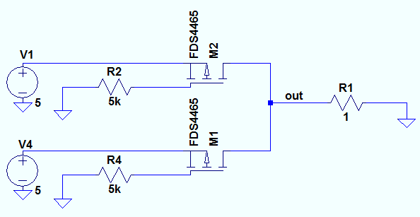
My intention is to design a or-ing power supply option, as either of them will be used at a time. Possible solutions are shown below:


Using oring diodes
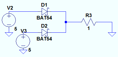
enter image description here
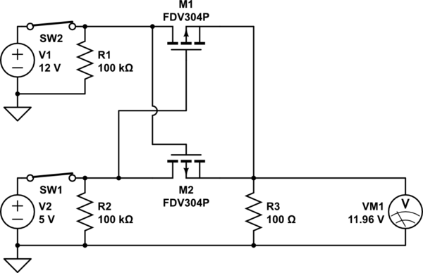
or using two p-mosenter image description here


Possible issues observed with the above options:

  • Using diode is cheap and good option but an ordinary diode gives a drop of 0.7V and a schottky diode will give a drop of 0.16 to 0.20 volts, which is also not acceptable because my processor IMX.28 recommended operating power supply is 5.0V and minimum supply voltage is 4.75. With a 0.2V with schottky diode the 5.0V comes down to 4.80V and the space between recommended and supply fed is very less.
  • Then I thought to use p-mosfets which serves the purpose of oring along with reverse polarity protection, but assume a case when both the supplies are fed together by mistake and there is minor difference between USB supply and DC jack say 4.9V for USB and 5.10V for DC Jack. Then, the DC jack supply may pump the current in USB Jack, which may damage USB.

Is there any other better and cheap option I should use for or-ing supply, or is there something wrong with my analysis?

\$\endgroup\$
6
  • 1
    \$\begingroup\$ If you are using a typical DC jack with 3 pins then I'm not sure anything extra is required, as IIRC without the jack inserted one of the pins is connected to the centre pin. With the jack inserted this disconnects. So you can use this pin to supply the USB power with no jack. \$\endgroup\$ Commented Jan 14, 2014 at 4:54
  • \$\begingroup\$ @geometrikal: can you you please suggest the part number for such jacks? \$\endgroup\$
    – AKR
    Commented Jan 14, 2014 at 16:12
  • \$\begingroup\$ @AKR He means this kind of plug but I'm not sure how it's going to revert to USB operation in case the DC plug is inserted but the mains power turns off. \$\endgroup\$
    – alexan_e
    Commented Mar 15, 2014 at 8:18
  • 1
    \$\begingroup\$ Related thread: electronics.stackexchange.com/a/57216/7036 . Related app note: Extending Single Input Charger to Dual Input Applications \$\endgroup\$ Commented Jul 14, 2014 at 20:43
  • \$\begingroup\$ Also note that the mechanical jack may interrupt one power source before connecting the other. \$\endgroup\$
    – gbarry
    Commented Jul 14, 2014 at 20:45

5 Answers 5

20
\$\begingroup\$

There are ICs available to do the whole thing, including the switching MOSFETs, full isolation between inputs, etc.

For example, the TPS2115A from TI can autoswitch between two inputs, handle 2A, and is currently available for US$2.15 from DigiKey. Take a look at figure 14 for what you want.

\$\endgroup\$
1
  • 2
    \$\begingroup\$ These is the way to go. Cheap, simple, versatile and reliable. Some of these ICs also allow to switch the source with a TTL or CMOS signal, turn off the output entirely and/or to read out which source is being used, which can be useful. They are called PMIC OR Controllers or Ideal Diodes. \$\endgroup\$
    – iFreilicht
    Commented May 19, 2019 at 20:04
17
\$\begingroup\$

I know this is a few months old, but just for posterity:

Using two PMOS as the OP suggests will NOT work as he intends. It's a mistake I've made in the past. The FETs will effectively do nothing to prevent one power source from back-feeding into another, as the intrinsic body diode will conduct from the drain to the source when under a reverse bias. See this posting to learn more about the body diode and how/why it is formed.

There are solutions with discretes (which invloves using mosfets with a 4th body terminal), but go ahead and trust me, they aren't very simple, and requires some consideration with circuit layout.

Edit: With the 4 terminal FETs you remove the body diode, so you only need one. I should mention that there is a solution using 3 terminal FETs by using two pmos in series, with their sources tied together. See this anwser and this app note. Google "fet common source switch" for more info.

The alternative is to use a PMIC (power management IC) as others have advised. They sell PMICs that have the functionality of an ideal diode (no voltage drop), and others that are more application specific. It really will simplify your life. They'll abstract away some of the device physics complexities, and handle them much more effectively than could be done using discretes. Checkout the TPS2114 as an example.

\$\endgroup\$
0
5
\$\begingroup\$

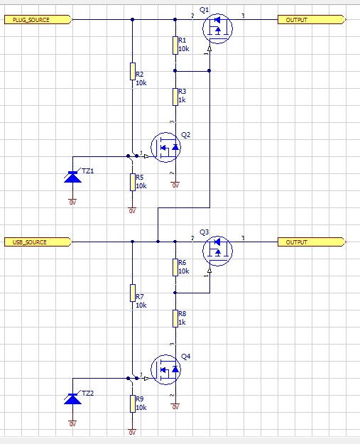
If you want to do it with discretes, you can augment the functionality of your FET arrangement as so:

enter image description here

This will turn on the appropriate FET when the appropriate source is connected.

I imagine that it would be favourable to prioritise the USB source for communications functionality so it takes precedence if both sources are connected by switching the Plug pack source off.

\$\endgroup\$
3
  • \$\begingroup\$ Adding an extra MOSFET will increase the price of the solution. I am looking for something cheap!!! \$\endgroup\$
    – AKR
    Commented Jan 17, 2014 at 9:33
  • \$\begingroup\$ You yourself already proposed M1/M2 in one solution. Q2/Q4 are not power FETs but BSS123's or the like. $2 worth of additional parts isn't cheap enough? \$\endgroup\$
    – Martin
    Commented Jan 18, 2014 at 10:43
  • 2
    \$\begingroup\$ Q1 and Q3 on the Answer 1 seems to be reversed. The body diode will conduct to the source from Output irrespective of the gate signal... \$\endgroup\$
    – user49355
    Commented Jul 14, 2014 at 20:37
5
\$\begingroup\$

As this question ranks quite high in search results for MOSFET power supply ORing, I'll add analysis of such.

Here is an actually working version of the two MOSFET circuit shown in question. I have flipped the MOSFETs so that the parasitic diode does not leak back to the input, and connected each FETs gate to the opposite voltage input.

schematic

simulate this circuit – Schematic created using CircuitLab

Now, this circuit does work, but it has a shortcoming. If both inputs have the same voltage (less than gate threshold of difference), both MOSFETs will remain off and conduction will be only through the parasitic diode. This will cause more voltage drop.

As such, it is suitable for either separate voltage levels (such as 12V and 5V inputs), or only as protection against rare misconnection (in which case it does not matter that voltage drops if both supplies are connected).

\$\endgroup\$
0
4
\$\begingroup\$

You might try "ideal diodes" such as https://www.digikey.com/product-detail/en/maxim-integrated/MAX40200AUK-T/MAX40200AUK-TCT-ND/7599791 -- for an ORing input solution, where you don't need a cut-over, it just might do the trick.

\$\endgroup\$
1
  • \$\begingroup\$ Thanks. I was looking about TPS2120 from TI, but @12V only BGA package is available. LTC4412 is cheaper and more available. \$\endgroup\$
    – Ben
    Commented Aug 30, 2023 at 7:59

Your Answer

By clicking “Post Your Answer”, you agree to our terms of service and acknowledge you have read our privacy policy.

Not the answer you're looking for? Browse other questions tagged or ask your own question.