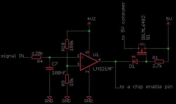
I have the following schematic (extract):

The purpose of this is to enable a pin (chip enable) and to disable the 5V supply ("5V consumer") if the threshold at the signal IN is above a certain threshold (VRef=0.5V). So far so good, the circuit works fine under "normal" circumestances.
The problem is that when I use the PCB with different power supply and input signals (for testing purposes), th op amp does not switch any more. Here are the differences:
- power supply:
- normally: USB(5V) -> battery charger IC -> 4.2V
- testing: 5V from Raspberry Pi -> battery charger IC -> 4.2V. In this case I noticed that the 5V are actually about 4.8V, but that's still enough. In both cases, no battery is connected so the battery charger is acting as a voltage regulator.
- signal IN:
- normally: analog audio signal with a bias voltage of 1.3V and no more than +/- 0.4V peak-to-peak voltage.
- testing: 1.3V DC voltage
So when testing, I measured the 1.3V at the signal IN pin and the 0.5V at the VRef pin of the op amp, but it did not switch, i.e. the chip enable pin remained low and the 5V consumer voltage was still enabled.
The total power consumption of the PCB is under 50mA, so it should not be a problem for the Raspberry Pi to power it. The power supply unit is also rated at 1000mA.
Any idea why this happens? Am I overseeing something? Thanks!
UPDATE
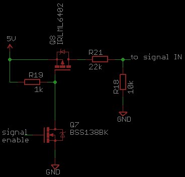
Maybe it's relevant, so I added the circuit which switches the ~1.4V at the signal IN pin:

One thing I noticed: while sweeping the input signal ("signal IN") from 0V to about 2V, I noticed that the op amp switches correctly above the threshold of about 0.55V, but the output voltage jumps from about -15mV (input under 0.55V) to about 60mV (input over 0.55V).
