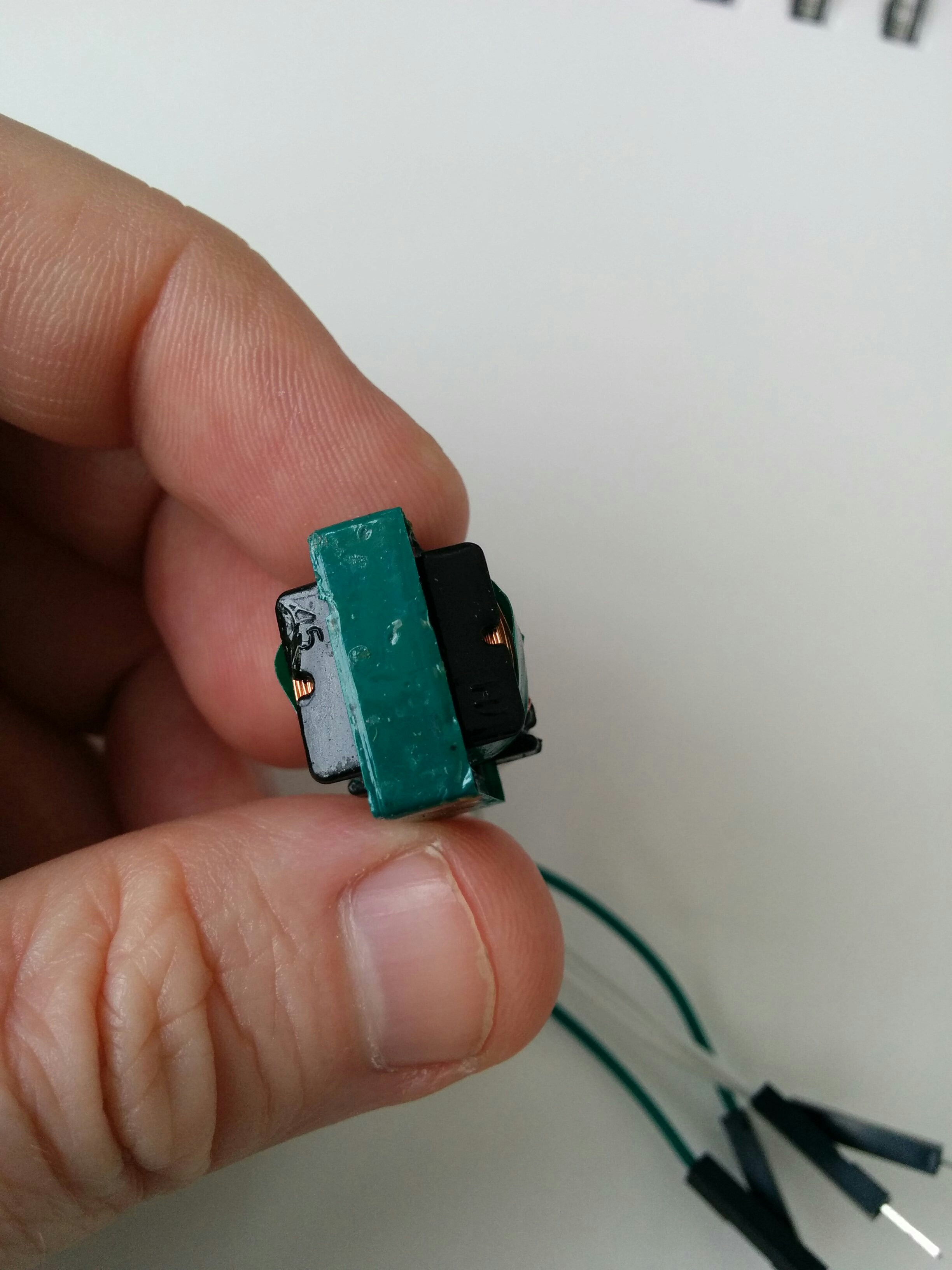
 Hi, I pulled this transformer from an EL wire inverter and am trying to figure out how to infer:
- Which pins correspond to the primary and secondary coils
- The ratio of the windings
- Any other useful information I can glean.
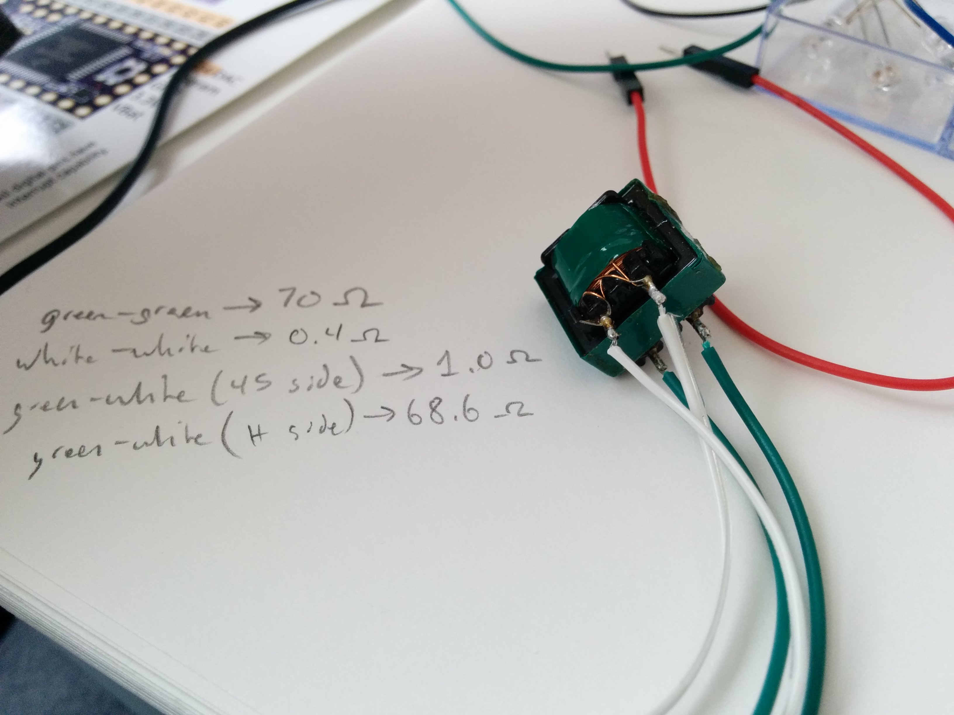
There are only two markings on the top, none on the bottom. The top markings appear to be "45" on one side and, catty-corner to that, an "H". the pins on the bottom are symmetrically aligned, not offset like some transformers I've seen. I checked the resistance between pins and found:
- Green-to-green: 70 ohms
- White-to-white: 0.4 ohms
- Green-to-white (side marked "45"): 1.0 ohms
- Green-to-white (side marked "H): 68.6 ohms
...for background, I'm trying to implement the circuits described in Disney Research's "Tesla Touch" and "Revel" works (I can't add links because I don't have enough points). The papers call for a flyback transformer that boosts 3-5v to about 300v, which is significantly less than the voltages needed by other plasma- and arcing-related flyback projects I've seen online.
My understanding was that EL wire takes about 600v at similarly small currents, which is why I pulled the transformer from an EL wire inverter. However, I'm having trouble getting reliable performance from the transformer and am hoping with this question to resolve some fundamental questions I have about the component.
Thanks in advance for any help you can provide!
AKA
