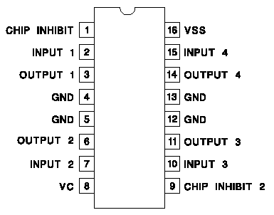
I've got a L293D and a PIC16F877A outputting PWM. Not real PWM, just using Timer0 to turn ON a pin for 2 ms and OFF for 18 ms (total of 20 ms period).

W.R.T. to the above schematic I got VSS, VC, CHIP 1 and CHIP 2 up to 5V.
My current method of controlling the motor is to turn input 1 and 2 on-off from the PWM, to control the outputs 1 and 2. My motor is a hacked servo motor that runs 360 degrees.
EDIT: My motor is a pre-hacked RC servo motor, specifically the Cytron C36S, hacked to run continuously (i.e. behave as a normal motor, no longer as a typical servo motor)
My approach
When input 1 is ON and input 2 is OFF, it prompts the motor to run one way, input 1 is not always ON. Since input 1 is the PWM output from the PIC, it'll turn ON (HIGH) for 2 ms and OFF (LOW) for 18 ms in continuous cycle of 20 ms.
But using this setup, my motor isn't properly working; sometimes it runs slower than usual (this is actually what I want) but most of the time it just hums in its place, no movement whatsoever.
How do I improve this configuration, is there a better way to control motor speed using L293D? If possible I want to use l293D as buying new components/ICs are too much of a hassle...
