If your instructor expects you to use opamps, then use them as comparators.
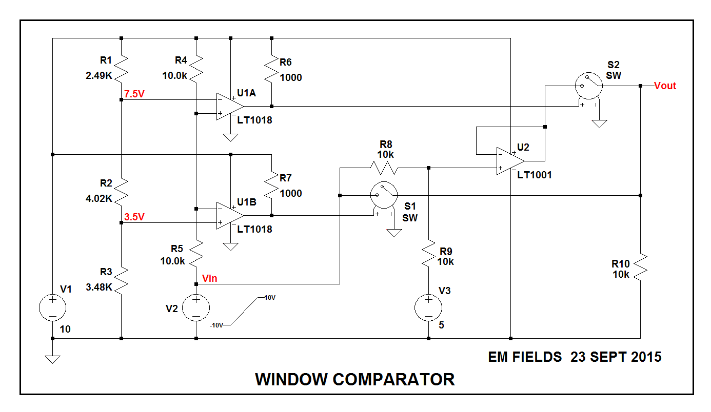
Following is a circuit which uses comparators to do what what you want, but you could just as easily substitute opamps. Here's how it works:
V1 is the 10 volt supply and V2 is the input signal and, having no information to the contrary, I've assumed, for the sake of the argument, that V2 it can vary from - 10 volts to + 10 volts.
U1A and U1B are the two comparators comprising an LT1017, and their inputs aren't allowed to go more than 300 millivolts below ground, so if a 10 volt supply is used for V1, then with R4 and R5 both equal to 10k, when V2 is at -10 volts the voltage at the R4-R5 junction will be zero volts.
Then, since V2 can only go more positive than -10 volts, the problem of driving the comparators' inputs below ground when V2 is negative is averted.
Next, the switching points must be determined, and they'll be the voltages at the R4-R5 junction (V3) when V2 is equal to minus 3 volts and when it's equal to 5 volts.
In order to find them we can write:
$$ V3 = \frac{(V1-V2)\times R5}{R4+R5} +V2 $$
Then, With V2 equal to minus 3 volts we'll have:
$$ V3 = \frac{(V1-V2)\times R5}{R4+R5} +V2 = \frac{13V\times 10k\Omega}{20k \Omega} -3V = 3.5\text { volts} $$
Similarly, when V2 is equal to 5 volts, V3 will be equal to 7.5 volts
In order to generate these voltages we use the resistor string R1,R2,R3 as a voltage divider, arbitrarily force 1 milliampere through it, and select the resistors to yield the trip point voltages we need for U1A and U1B.
Since V1 is 10 volts and we need 7.5 volts for our high trip point, R1 needs to drop the difference, 2.5 volts, with 1 milliampere through R1. Using Ohm's law we can write:
$$R1 = \frac{V1-7.5V}{1mA} = 2500 \text{ ohms}$$
Selecting the closest E96 value, we'll choose 2490 ohms for R1
With the bottom of R1 at 7.5 volts and our next switching point at 3.5 volts, we'll need to drop 4 volts across R2, and with 1 milliampere through it, the E96 value closest to 4000 ohms will be 4020 ohms.
Finally, with the remaining 3.5 volts left to be dropped across R3, the E96 value closest to 3500 ohms will be 3480 ohms.
Now, as V2 slews from -10 to +10 volts, when it starts, U1B+ will be more positive than U1b-, forcing U1B's output high. That'll turn S2 ON, connecting V2 to R10. Also, since U1A+ will be less positive than U1A-, U1A's output will be forced low, turning S1 OFF.
This state of affairs will continue until V2 goes more positive than -3 volts, at which point U1B- will go more positive than U1B+ which will force U1B's output low and turn OFF S2. At this point S1 and S2 will both be turned OFF, and Vout will be pulled down to ground through R10.
As V2 continues to go more and more positive, eventually it'll get to 5 volts, at which time U1A+ will go more positive than U1A- and U1A's output will go high, which will turn S1 ON and connect the junction of R8 and R9 to U2+.
Since V2 and V3 vill now both be at 5 volts, U2+ will also be at +5 volts, and since U2 is a voltage follower, its output will be at 5 volts, which will be connected to R10 through the now closed S2.
Since R8 and R9 have equal resistances, as V2 rises above 5 volts, the voltage on U2 will rise at half that rate, satisfying the requirements for the slope above 5 volts.
R8 and R9 comprise a voltage divider with their junction
So, the result of all this is that V2 will be connected to R8 from the time it's between -10 volts and -3 volts, then as it goes more positive than -3 volts R8 will be disconnected from V2 until V2 gets to 5 volts, when R8 will again be connected and will stay connected for as long as V2 stay more positive than 5 volts.
Here's the drawing, and if you want to play around with the circuit, here's the LTspice .asc file so you can simulate it.

