EDIT - you say the gain of the opamp is okay. Looking at the rest of the circuit, I agree with Russell completely - it needs fixing, follow his instructions and it will work (if there are no other hidden problems)
Also, you need to get your power supply right - as you don't actually show a power supply it's impossible to know what you are doing currently (for the components not connected to the arduino 5V line)
There is nothing connected to the ground ports on the Arduino apart from the top pots. You have a ground symbol (marked "GND") connected to e.g. the LEDs, etc but where is the common connection to the Arduino?
Updating your schematic to show everything exactly as is regarding power supply connections would be very useful (i.e. add Arduino power source, opamp and 4066 power pins/connections, etc)
I'll leave the below opamp gain section here anyway. It would be worth fixing the schematic to include junction dot to indicate things clearly.
You say you want to change 0V-5V to 0V-10V, so you need a gain of 2.
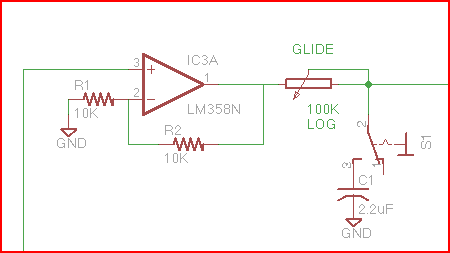
Now the opamp circuit you have shown should give a gain of 2, but it doesn't. Why?
My suspicion is that the junction dot between R1, R2 and opamp inverting input was missed out on the schematic, so there is no connection on the final board.
I checked the large version and looked at another junction. You can clearly see the junction dot between the 100K pot and S1, but none at R1-R2:

The lack of a dot may mean that R1 is not connected (only R2) which will give the opamp a gain of 1, not 2.
This is just a guess as I don't know eagle well enough to tell whether it should be like that if the nodes of a component are directly together.
Anyway, it's worth checking to see if you have connectivity between opamp inv and R1.
