Further to my previous question, Using a PIC to perform switch on and timed shutdowns in automotive environment
I've been pointed at zener diodes and voltage dividers, but I'm now confused by the PICs builtin weak pull-up resistors (and if I check the datasheet, values are TBD... I assume something like 10k?)
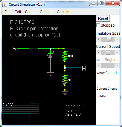
So the PIC input pin protection circuit I think I have understood is this:
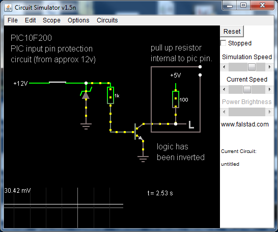
But using weak pullups, I think I could do this:

But all this does is swap a resistor to a transistor.
Update
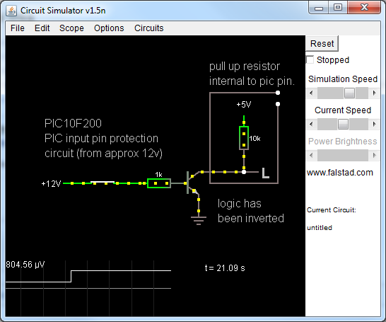
Further to comment from @PJC50, I now think the circuit utilising the PIC's pullup resistors would look like this:
 It's now clear why I should do this and how it reduces component count.
How do I choose a resistor and transistor that are suitable?
- Is the voltage divider circuit correct?
- Is the circuit that uses the weak pullups correct? (i think not)
- Why would I use pullups over normal voltage divider?
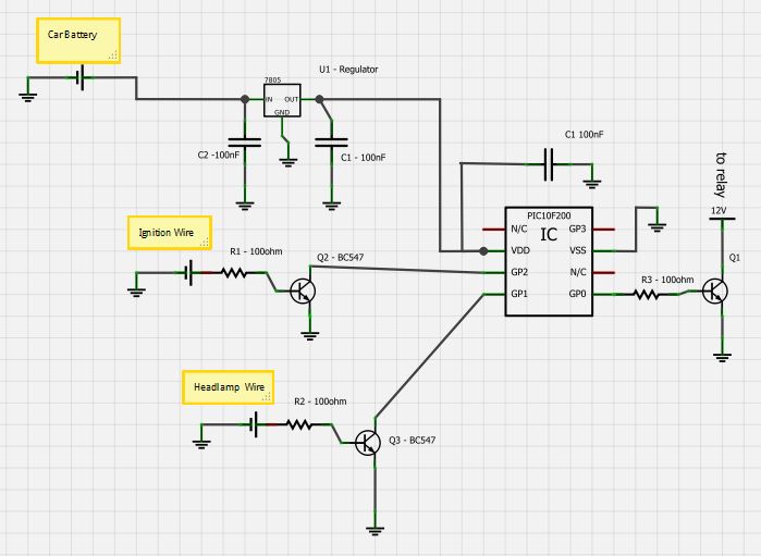
So my new circuit looks like this:

Update 2:
I've tested the circuit with pull ups, and I think I'm getting closer to real solution, any further comment/critique welcome! My circuit now looks like this:
