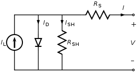
Figure 1. The equivalent circuit of a solar cell. From Wikipedia's Theory of solar cells.
To understand the electronic behavior of a solar cell, it is useful to create a model which is electrically equivalent, and is based on discrete ideal electrical components whose behavior is well defined. An ideal solar cell may be modelled by a current source in parallel with a diode; in practice no solar cell is ideal, so a shunt resistance and a series resistance component are added to the model. The resulting equivalent circuit of a solar cell is shown on the left. Also shown, on the right, is the schematic representation of a solar cell for use in circuit. [Emphasis mine.]
If the solar cell is behaving as a constant current source then it doesn't matter how many you put in series, you can only get IL from the combination. If, for example, IL = 1 A then two or more panels in series will give 1 A into a short circuit.
If you don't short-circuit the panels and allow them to work at their optimum point - maybe 12 V and 0.5 A, for example then the series connection will give out 24 V @ 0.5 A and the power into the load will be twice the power of one panel. Note that your load resistance will have to be double that of the 12 V load.
From the comments:
If we leave the short circuiting aside and assume a solar panel connected to 10 ohms draws 1 A . And if we connect another panel in series to same 10 ohms would it draw 2 A? Assuming both panels are capable of providing more than 1 A according to load.
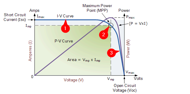
Figure 2. Solar cell I-V curve. Modified from source: Alternative Energy Tutorials.
The I-V (current vs voltage) curve of the solar panel is required to answer this question. Starting at the Open Circuit point on the V-axis we can see from the blue I-V curve that as we increase the current drawn from 0 A the voltage starts to decrease. At the maximum power point the curve is turning almost horizontal and it has gone into current limit and the voltage collapses. The purple P-V curve shows us that maximum power will be obtained at MPP and that is where you try to operate for maximum efficiency.
If you were to run your 12 V panel into a 10 Ω load and it happened to be operating at point (3) then if we double the load (half the resistance - which is the same effect as your comment) the current would increase to that at (2) but the voltage would drop to maybe 90%. Your power out would be less than double: it would have gone from \$IV\$ to \$2I \times 0.9 V\$ or 80% extra. Note that you if you were operating at (1) then you were were not operating the panel efficiently.
If you were operating at (2) and tried to increase the current the voltage will collapse as shown at (1).
Relative to (1) current has doubled but voltage has collapsed to 50%. Now instead of \$ P_2 = VI \$ you have \$ P_1 = \frac {V_2} 2 2I_1 \$ which is the same power you started with.
Relative to (2), the optimum, I has gone up about 10% but V has collapsed to < 50%. Now \$ P_1 = 1.1 \times I \times \frac V 2 = 0.55 P_2 \$.


