Custom regulator
Build your own linear regulator to get the flexibility you want, you won't need anything advanced here.

simulate this circuit – Schematic created using CircuitLab
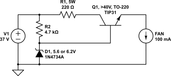
Q1 is an emitter follower and R2+D1 sets the output voltage, which has to be about 0.6 to 1 V higher than what you want, because of the voltage drop through Q1's base.
R1 is optional and is just there to take some heat off of the main transistor. It may be easier to keep a power resistor cool or within limits, than it is to keep the transistor cooled. Without R1, Q1 will have to dissipate 3 watts, which requires a heat sink. If R1 is installed, Q1 should only dissipate 1 watt at most. R1 also acts as a crude current limiter, because the voltage will drop too much at high currents.
I just picked Q1 from something that seemed reasonable and existed in circuitlab. Which one you can get varies depending on where you live and where you order your components. It must be able to handle the voltage, current, and a couple of watts.
It's worth noting that no matter what you do, using a linear regulator such as this, a 7805, or an LM317, will necessarily create at least 3.2 watts of heat as losses, while delivering 0.5 watts to your fan. It does not scale well with multiple fans in parallel either, seeing how you would have to remove a lot of heat somehow.
Better solution
I noticed this:
[…] powering some cooling fans […]
If you have more than one fan, you should connect as many of them as you want in series, the optimal being 3 x 12 volt fans which you can connect directly to your unregulated supply.
