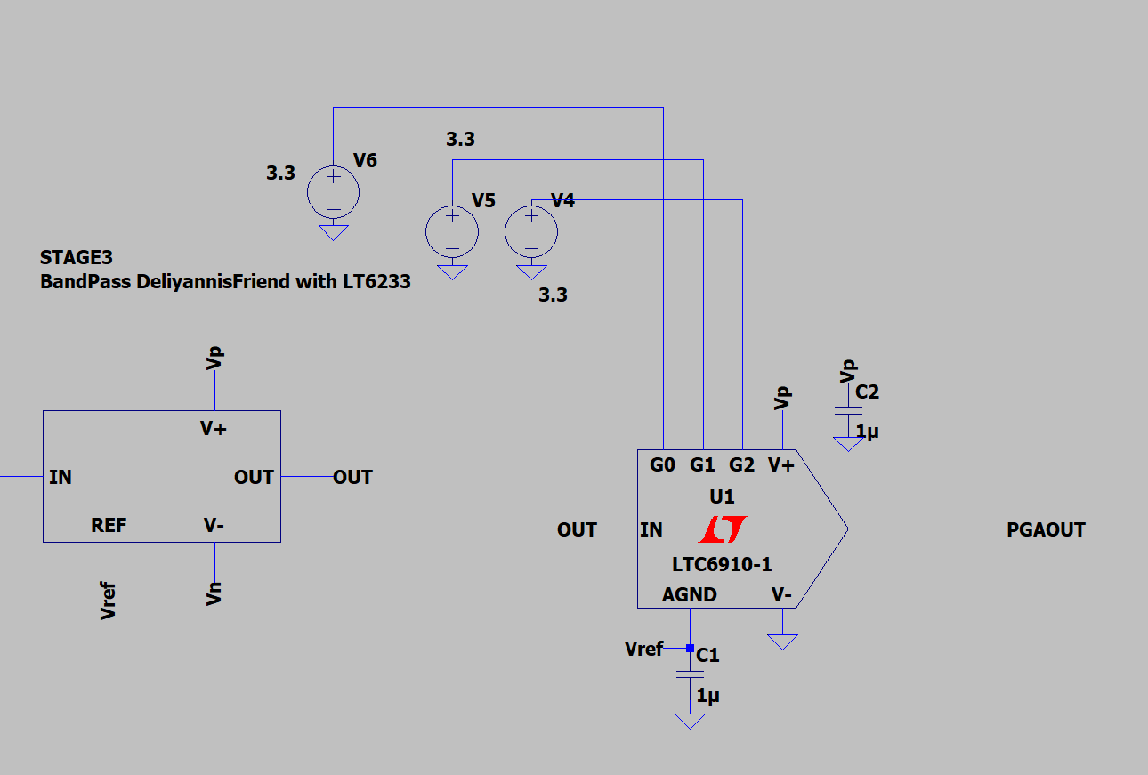
I'm trying to design a band pass filter with a programmable gain option to record varying levels of sound as defined from a microcontroller. I used LTspice to design my circuit the filter portion of my circuit works as expected.
The signal output is centred at 1.65v which is what I want.
My problems start when I try to use the LTC6910-1 PGA. Looking at the data sheet, the gain seems to be inverting but I'd just like a simple non-inverting gain which can then be adjusted based on the G0, G1 and G2 pins. My example circuit looks like this
where OUT is the filter output , Vp is 3.3V and Vref is 1.65V. The output from the PGA looks like this for a gain of 100.  I'd just like something centred across the mid 1.65V but I'm not sure how to make the circuit non-inverting.
Is this possible with this circuit? If not, has anyone got any other recommendations?

