I'm struggling to understand the exact circumstance where this would be needed.
What most folk want with a common emitter amplifier is for the DC collector voltage to be about half the supply voltage. So, when you have an AC signal present at the input, the amplifier's output (collector) doesn't clip the signal asymmetrically. Another way of phrasing it is that you are aiming for a good linear dynamic range capability.
To achieve this, you need to create a situation where the DC quiescent collector current is held fairly constant. So, if Vcc is (say) 12 volts and Rc is (say) 2200 Ω then you want the quiescent current through Rc to be about 2.73 mA (2.73 mA through a 2k2 resistor drops 6.006 volts).
To ensure that a DC current of 2.73 mA flows through Rc consistently requires an emitter resistor. If the emitter resistor is 220 Ω (for example), a DC current of 2.73 mA flows from the collector into the emitter and then through the resistor and, it would drop about 0.601 volts across it.
It then follows that the base-bias voltage would need to be about 0.601 volts plus about 0.7 volts (internal base-emitter volt-drop). So, around 1.301 volts on the base will ensure that there is approximately 6 volts DC at the collector.
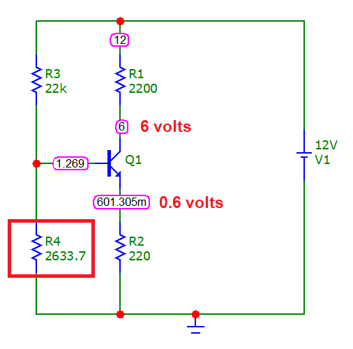
Knowing this allows you to calculate the base-bias resistor values. Here's a simulation where I've tweaked R4 to show what I mean: -
In this example I used a BC547 BJT and the base voltage to ground is 1.269 volts (implying that the base-emitter volt-drop is 0.669 volts). So, it's easy to follow and you should nearly always get predictable results but you'll never get exact results from a single BJT amplifier.
So, that's the normal case when an emitter resistor is used.
If you didn't have an emitter resistor, how can you properly define the current flowing in the emitter (and the collector)? Well, you can if you know the maths surrounding a CE configuration but, then you'll find that temperature effects will be surprisingly high and the desired 6 volts at the collector may drift with temperature a few volts this way and that way.
So, do you want a 5h1tty circuit that drifts around or, do you want a stable circuit?
But I'm struggling to understand the exact circumstance where this would be needed. Is it a change in supply voltage, or change in transistor beta?
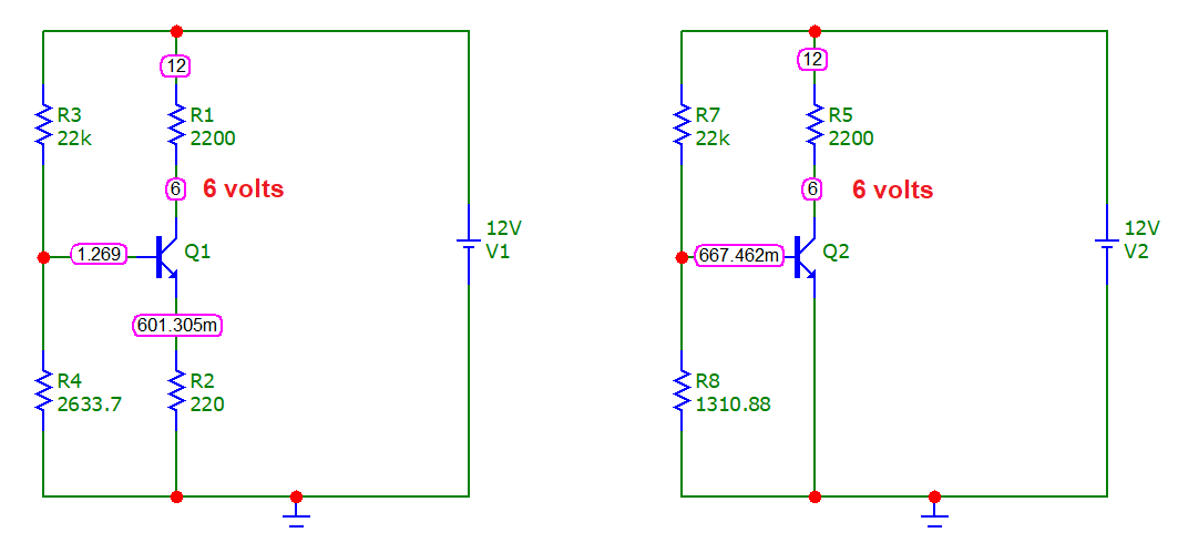
It's both and, it's also temperature and, it's also circuit repeatability. Here's a side by side comparison: -
And, if I increased R4 in the left circuit and R8 in the right circuit by 5% we would see this: -
Can you see that a very small change in the biasing condition hasn't really altered the quiescent DC voltage on the left-hand circuit but, on the right-hand circuit, the collector voltage has dropped from 6 volts to 188 mV. The right-hand circuit is very susceptible to component drift.
If I restore the resistor values and increase the power supply voltage from 12 volts to 13 volts here's what we see: -
In other words, the right-hand circuit is very susceptible to power voltage changes (and also component value changes). If I restore the supply voltage to 12 volts and change the ambient temperature in my simulation from 27°C to 37°C we see this change: -
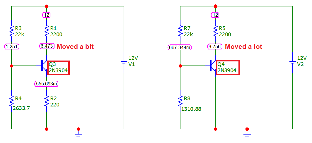
In other words, the right-hand circuit is very susceptible to power voltage changes, component value changes and ambient temperature changes. But, what if I swapped out the transistor with a 2N3904: -
The above has restored ambient back to 27°C but swapped the BC547s for 2N3904s. The circuit on the left is clearly more robust at dealing with this situation.


