Question
MCU STM32 with stepper motor driver Allegro A4988 are moving a 2 coil, 4 wire, bipolar stepper motor ridiculously slowly, with flickers and stutters. How to fix?
The OP's original code (See Appendix A, B, and C below)
Answer
Contents
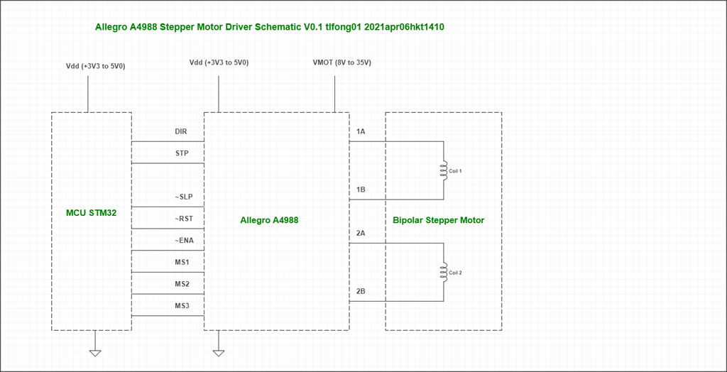
1. The MCU + Driver _ Motor Schematic V0.1
2. The OP's STM32 C++ Test Code Analysis
1. The MCU + Driver + Motor Schematic v0.1
2. The OP's STM32 C++ Test Code Analysis
I skimmed the OP's three short functions and found them more or less OK, though I did not go step by step in detail to detect any bug.
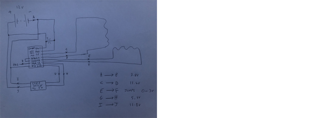
I think I better test the A4899 driver and motor independently off line, without using any STM32 C++ code, but just use a NE555 timer to simulate the step pulses, and jumper wired by hand for inputting signals.
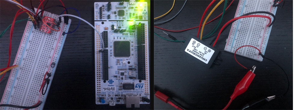
3. Offline (by hand without STM32 code) testing A4899 and motor, using an NE555 timer to simulate step pulses
3.1 Now I am read the A4988 datasheet, checking out the operation and timing requirement, to make sure the timing of the OP's code is OK.
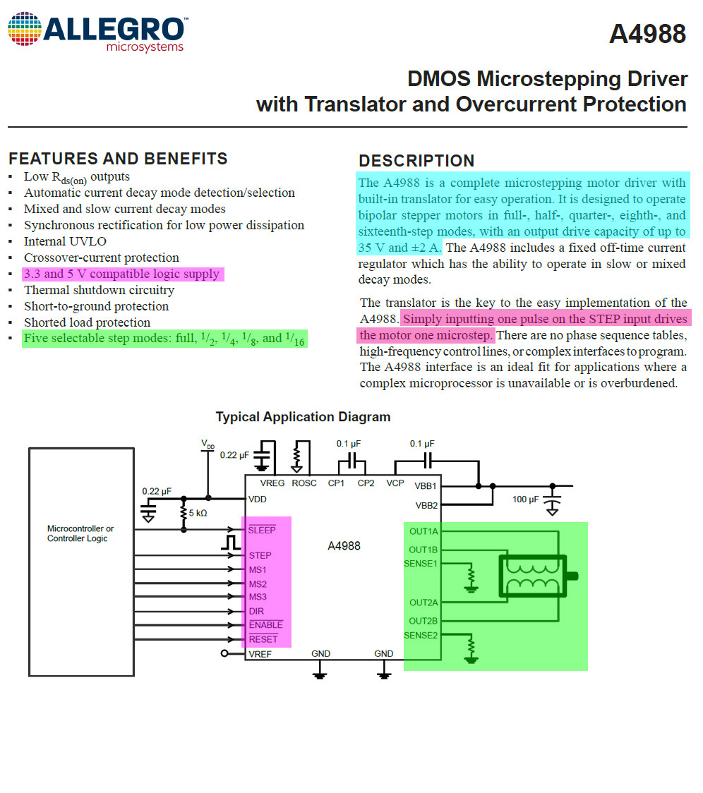
(2) A4988: DMOS Microstepping Driver with Translator and Overcurrent Protection - Allegro
/ to continue, ...
References
(1) A3988: Quad DMOS Full Bridge PWM Motor Driver Datasheet - Allegro
(2) A4988: DMOS Microstepping Driver with Translator and Overcurrent Protection - Allegro
(4) Control of Stepping Motors A Tutorial - Douglas W. Jones, CS Dept, U Iowa 1995
(5) Stepping Motors Fundamentals AN907 - MicroChip 2004
/ to continue, ...
Appendices
Appendix A - The OP's Original Code - main.c
#include "./headers/stm32f767xx.h"
#include <stdint.h>

int main(void)
{
    initMotor(0); // initialise the motor
    initLed(7); // initialise the led
    unsigned long a = 0;
    while (1)
    {
        if (a == 50000)
        {
            toggleLed(7); // this LED flashes a little quicker than twice per second
            stepMotor(0); // output a pulse to the driver to step the motor, attached to PA2
            a = 0;
        }
        a++;
    }
}
Appenidx B - The OP's Original Code - ./drivers/led.c
    #include "../headers/stm32f767xx.h"

    void initLed(int pin)
    {
        RCC->AHB1ENR |= RCC_AHB1ENR_GPIOBEN; // enable the GPIOB clock
        GPIOB->MODER |= (0x1 << (pin * 2)); // set to output
        GPIOB->OTYPER = 0x00; // push-pull mode
        GPIOB->ODR = 0x00; // set output register to 0 across all pins
    }

    void toggleLed(int pin)
    {
        GPIOB->ODR ^= (0x1 << pin); // toggle the pin
    }

---
Appenidx C - The OP's Original Code - ./drivers/motor.c
---

#include "../headers/stm32f767xx.h"

void initMotor(int step_pin)
{
    RCC->AHB1ENR |= RCC_AHB1ENR_GPIOAEN; // enable the GPIOA clock
    GPIOA->MODER |= (0x1 << (step_pin * 2)); // set to output
    GPIOA->OTYPER = 0x00; // push-pull mode
    GPIOA->PUPDR |= (0x2 << (step_pin * 2)); // pull down the pin specified
    GPIOA->ODR = 0x00; // set output register to 0 across all pins
}

void stepMotor(int step_pin)
{
    GPIOA->ODR |= (1 << step_pin); // output to the pin specified
    GPIOA->ODR &= ~(1 << step_pin); // reset the output back to 0
}
Appendix D - Troubleshsooting the OP's A4899 Test Code v0.1
I skimmed the OP's three functions and found them in general more or less OK, although I did not go step by step to detect any bug. I think I better test the A4899 driver and motor independently off line, without using any STM32 C++ code, but just use a NE555 timer to simulate the step pulses, and jumper wired by hand for inputting signals.
1. Main Funtion

1.1 Initialize GPIO pins interfacing motor
1.2 Initialize the status LED pin
1.3 Repeatedly (a) Toggle LED pin, (b) Send one step pulse


##############################################################################

# Appendix A - The OP's Original Code - main.c

#include "./headers/stm32f767xx.h"
#include <stdint.h>

int main(void)
{
    initMotor(0); // initialise the motor
    initLed(7); // initialise the led
    unsigned long a = 0;
    while (1)
    {
        if (a == 50000)
        {
            toggleLed(7); // this LED flashes a little quicker than twice per second
            stepMotor(0); // output a pulse to the driver to step the motor, attached to PA2
            a = 0;
        }
        a++;
    }
}

##############################################################################

Appenidx B - The OP's Original Code - ./drivers/led.c

    #include "../headers/stm32f767xx.h"

    void initLed(int pin)
    {
        RCC->AHB1ENR |= RCC_AHB1ENR_GPIOBEN; // enable the GPIOB clock
        GPIOB->MODER |= (0x1 << (pin * 2)); // set to output
        GPIOB->OTYPER = 0x00; // push-pull mode
        GPIOB->ODR = 0x00; // set output register to 0 across all pins
    }

    void toggleLed(int pin)
    {
        GPIOB->ODR ^= (0x1 << pin); // toggle the pin
    }

###############################################################################

# Appenidx C - The OP's Original Code - ./drivers/motor.c


#include "../headers/stm32f767xx.h"

void initMotor(int step_pin)
{
    RCC->AHB1ENR |= RCC_AHB1ENR_GPIOAEN; // enable the GPIOA clock
    GPIOA->MODER |= (0x1 << (step_pin * 2)); // set to output
    GPIOA->OTYPER = 0x00; // push-pull mode
    GPIOA->PUPDR |= (0x2 << (step_pin * 2)); // pull down the pin specified
    GPIOA->ODR = 0x00; // set output register to 0 across all pins
}

void stepMotor(int step_pin)
{
    GPIOA->ODR |= (1 << step_pin); // output to the pin specified
    GPIOA->ODR &= ~(1 << step_pin); // reset the output back to 0
}

##############################################################################
Appendix D - A4899 Stepper Motor Driver Module
Description
This product is a breakout board for the Allegro A4988 DMOS Microstepping Driver with Translator and Over Current Protection.
This stepper motor driver allows you to operate bipolar stepper motors in full-, half-, quarter-, eight-, And sixteen-step modes, with an output drive capability of up to 35V and 2A.
The translator is the key to the easy implementation of the a4988.
It suffices to insert an impulse on the step input to operate the motor with a microstep.
There are no phase sequence tables, high frequency control lines, or complex interfaces to program.
The A4988 interface is ideal for applications where a complex microprocessor is unavailable or is overloaded.
Characteristics
Simple step and direction control interface
Five different step resolutions: full step, half step, quarter step, eight step and sixteen step
Adjustable current control allows you to adjust the maximum current output with a potentiometer,
That allows you to use voltages above the rated voltage of your stepper motor to achieve higher stepping rates
Intelligent chopping control that automatically selects the correct current decay mode (fast decay or slow decay)
Overheat thermal shutdown, undervoltage lockout and cross current protection
Protection against ground short circuits and short circuits
Warning
Connecting or disconnecting a stepper motor while the driver is powered can destroy the driver. More generally, rewiring something while it is being supplied with power causes problems.
/ to continue, ...

