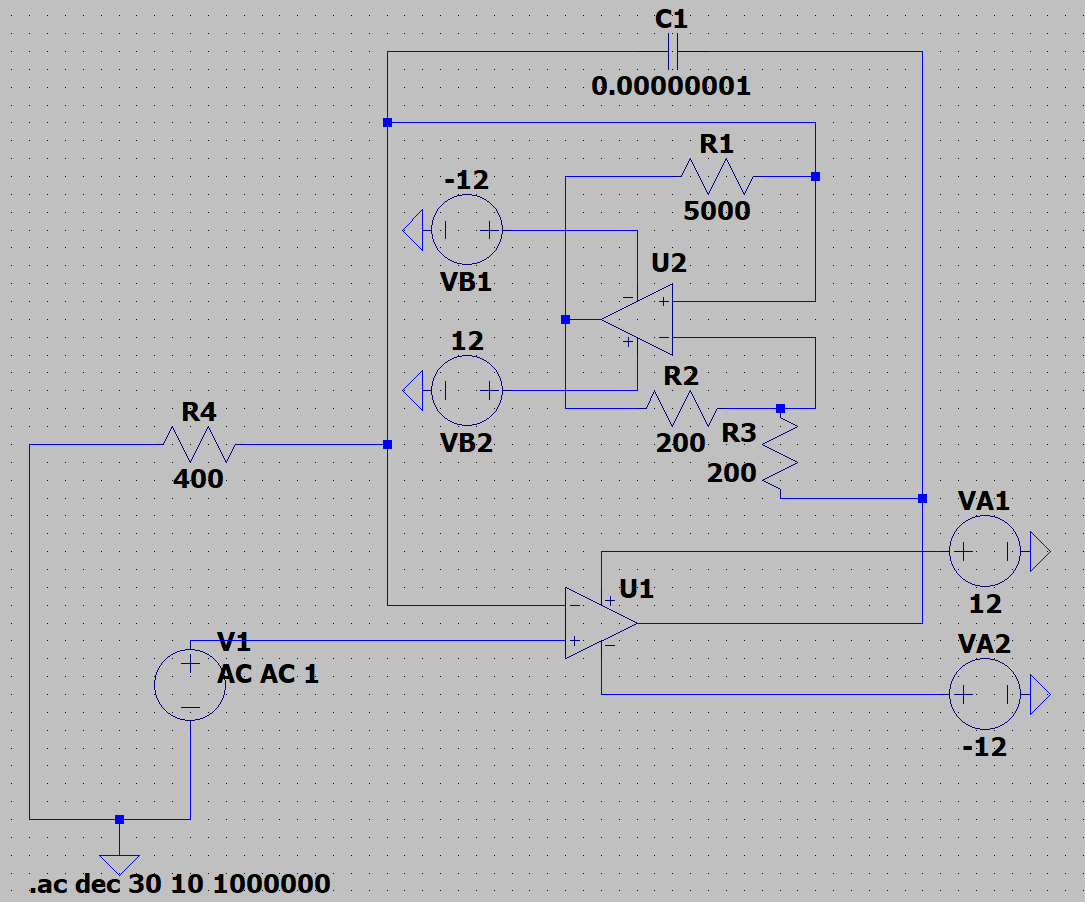
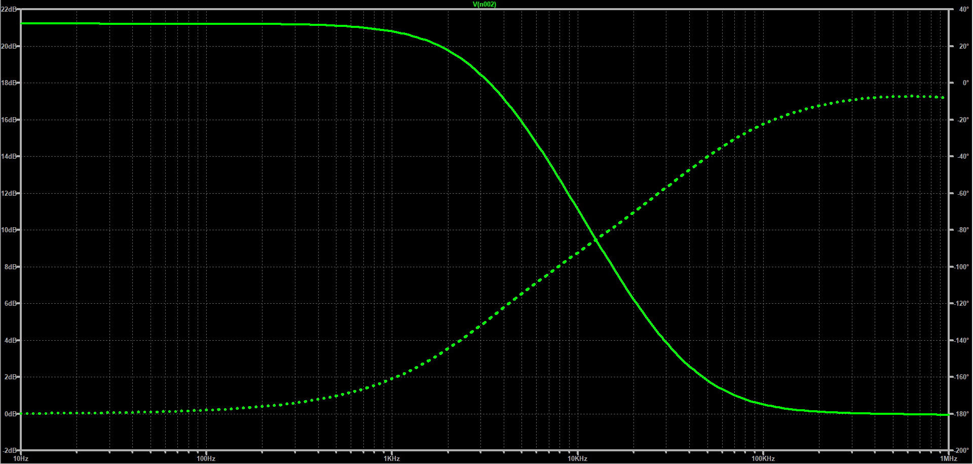
I've been trying to invert the phase response of a non-inverting low pass filter by using a "negative resistor" (-5000 Ohms), which is achieved by the simulation below (bode plot + circuit):

However, when I built the circuit (using LM358 op amps), the NIC makes the original low pass filter circuit lose its output signal. (I've also noticed that the NIC makes the power supply for the first op amp, U1, behave erratically - i.e. the negative voltage supply pings left when I turn on the positive voltage supply) I use a different power supply for each op amp, and the power supply pins on both op amps have decoupling capacitors in place. Could the NIC circuit just not be usable in the actual circuit?

