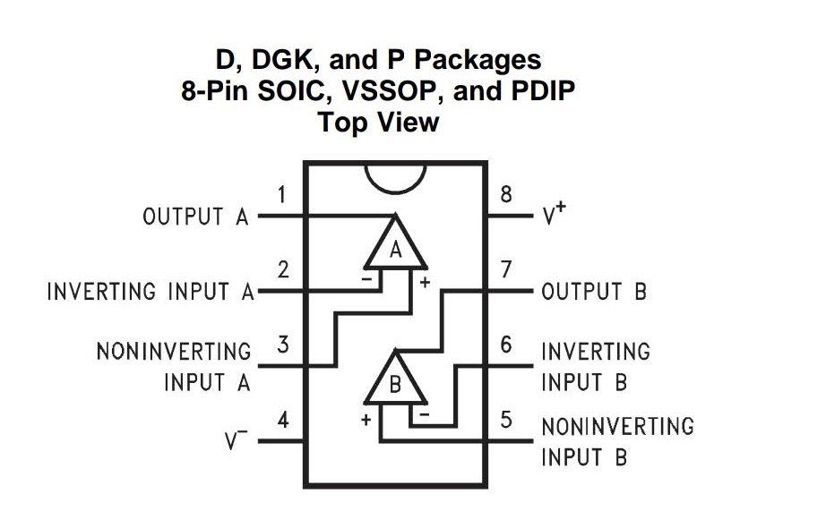
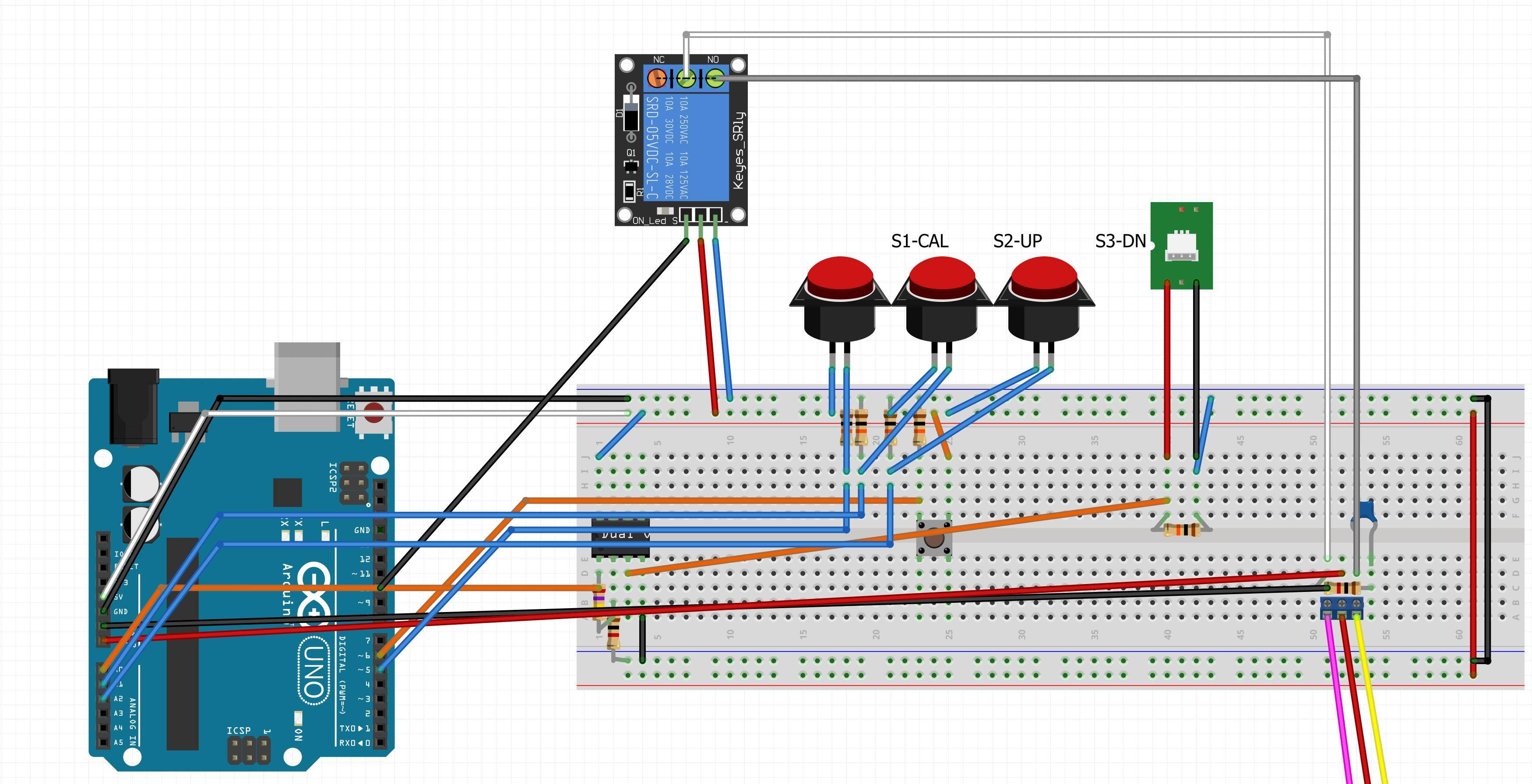
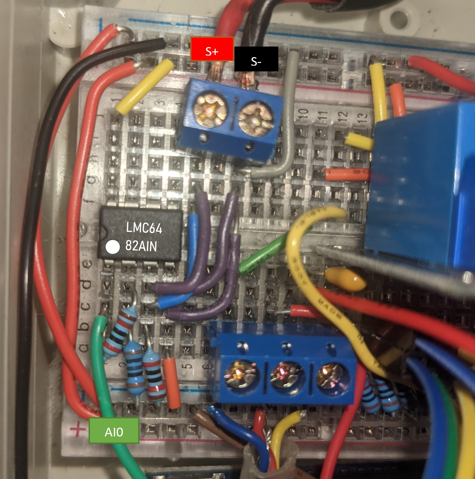
I'm building a control panel for an old altitude training machine and I need to measure the output of an oxygen sensor with an arduino. The oxygen sensor (medical oxygen sensor OOM202) is a micro fuel cell which outputs a voltage between 200μV and 20mV depending on the oxygen level. I'm using a LMC6482 CMOS dual rail-to-rail op amp running on a supply of 5 volts to amplify the signal before feeding it into the analogue input of an Arduino Uno. The resistor connecting pins 1 and 2 is 270kΩ and the resistor connecting pin 2 to ground is 1kΩ, though later I changed these to 20kΩ and 100Ω respectively (to no avail).
I've done about as much as I can to reduce noise and interference in the circuit, but the op-amp is behaving weird. I've measured the voltages of each of the pins and got the following:
- Pin 1: 185mV
- Pin 2: 29mV
- Pin 3: 13.8mV
- Pin 4: 0mV
- Pin 8: 4.92V
I have confirmed the resistances between the pins is what I expect:
- Pin 3 to Pin 4 (with sensor disconnected): 20kΩ,
- Pin 1 to Pin 2: 20kΩ,
- Pin 2 to Pin 4: 100Ω
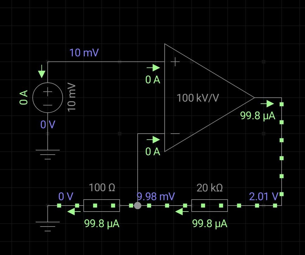
What am I doing wrong? My calculations say the output at Pin 1 should be around 2V.


