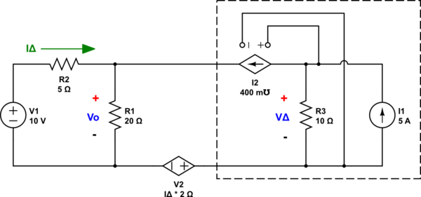
Need to correct a few details:
Segue
I've already explained in comments about a point of view I could suggest that is congruent with your quoted source. But you then write:
Won't the current from the voltage with the 2idelta' value below not pass through the 10 ohm resistor? And because of that we will find new voltage value on the right top?
Your question is apt. And it motivated me to write because the answer to your question is actually interesting.
The current in the dependent voltage source is zero
The current in the dependent voltage source, the one whose voltage is \$2\cdot i_\Delta\$, cannot be anything other than zero Amps. And it's obvious from the most basic inspection of the circuit.
And since you don't have part numbers in your schematic and if I don't assign them then I can't even talk to you, I am forced into laying out the schematic myself.
(Let this be a lesson to use the schematic editor and not to take the easy way out when asking questions by just pasting pictures.)
Here it is:

simulate this circuit – Schematic created using CircuitLab
(It turns out that soon enough we are going to analyze the stuff within that box over on the right.)
You can trivially determine that the current in \$V_2\$ must be zero. An ideal current source has an impedance magnitude of \$\infty\$. And \$I_2\$ is such a source. As such and because \$I_2\$ depends entirely on the voltage across \$R_3\$, it's simply not possible for there to be anything other than zero current in \$V_2\$.
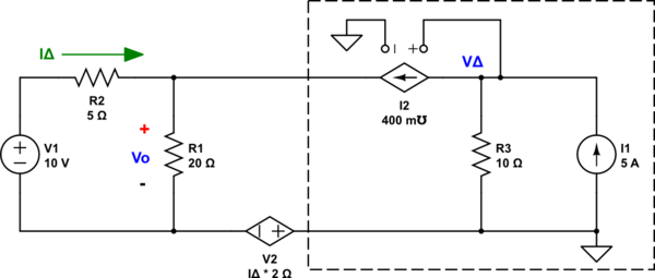
If you need a mathematical approach to convince you, then all you need to do is assign ground as shown here:

Look at the KCL for \$V_\Delta\$: \$\frac{V_\Delta}{R_3} + 0.4\:\mho\cdot V_\Delta= 5\:\text{A}\$. This instantly solves out to \$V_\Delta=10\:\text{V}\$.
There is \$1\:\text{A}\$ in \$R_3\$ and all the rest must be going out through \$I_2\$. And there is no room for the addition of any current through \$V_2\$. Everything is already determined by \$I_1\$, \$I_2\$, and \$R_3\$. And nothing can be changed there.
It won't matter where you put ground, either. None of this changes the above conclusion, which remains no matter how you look at the circuit.
There simply cannot be any current in \$V_2\$. It's not possible. So in answer to your question in the segue, there's no current in \$V_2\$. End of story. Done.
So where does this leave us?
We can now reduce the circuit further:

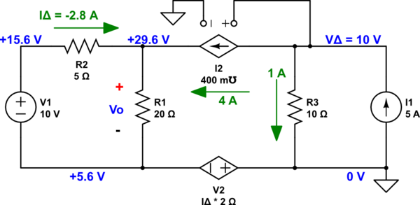
This solves out trivially to \$V_\Delta=24\:\text{V}\$, \$I_\Delta=-2.8\:\text{A}\$, and \$V_{\Delta\text{( - )}}=-5.6\:\text{V}\$.
Do take note here that \$V_\Delta\$ is a voltage difference across \$R_1\$. If it isn't already obvious, I just moved the ground around to make things still easier. I can do that. But shortly, you will need to remember this detail when I move the ground back to where I earlier had it.
Plugging all this back into the original schematic, and keeping the original ground reference that I earlier added, we find:

Now, recall my earlier warning when I moved the ground to make things still easier? I said to take note here that \$V_\Delta\$ is a voltage difference across \$R_1\$? Well, this is when you need to remember this, again. We do still have a \$24\:\text{V}\$ difference across \$R_1\$. But because I moved the ground back to a different node than when that difference was calculated, the two ends of \$R_1\$ are at different voltages with respect to ground. But the situation is still unchanged.
You are free to choose a different ground reference. But it won't change the currents in any way or the voltage differences between the nodes.
