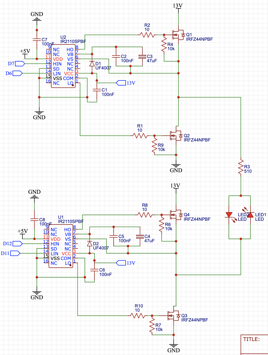
Here is my circuit:
When I start on phase 1 by PWMing LIN & HIN of U2 and send a HIGH signal to LIN of U1, then the circuit works perfect and only one LED lights up.
When I try to switch to phase 0 (after starting on phase 1) by PWMing LIN & HIN of U1, and send a HIGH signal to LIN of U2, then the MOSFET bridge suddenly shorts and breaks both of my IR2110 ICs.
BUT if I turn my DC power supply down to 0 volts, reset the Arduino to start on phase 1, and turn the DC power supply back up to 13V then the other LED lights up without a problem. For some reason my MOSFETs are only shorting when I try to switch phases, if I start on either phase 1 or phase 0 then it works perfectly.
Anyone know why this would happen? I am implementing 10us of dead time between switching phases so I don't think shoot through would be the problem.
Here is the code I am running:
int value = 100;
byte preg = 2;
byte sec = 0;
byte pres = 0;

void setup() {
  DDRB = B11111111;
  DDRD = B11111110;
  // I have an LED connected to pin A0 to help me determine
  // button presses
  pinMode(A0, OUTPUT);
  digitalWrite(A0, LOW);
  pinMode(A5, INPUT);

}

void loop() {
  // This code is to debounce a button press when for switching
  // phases
  sec = digitalRead(A5);
  if (sec == 0) {
    // Wait 1 second to check if button is still pressed
    delay(1000);
    sec = digitalRead(A5);
    if (sec == 0) {
      pres = digitalRead(A0);
      if(pres == 1) {
        // Set phase 0
        preg = 0;
      } else if (pres == 0) {
        // Set phase 1
        preg = 1;
      }
    }
  }

  // Switch to the new phase when button is pressed
  switch(preg) {
    // Phase 0
    case 0:
      PORTB = B11000000;
      PORTD = B00000000;
      digitalWrite(A0, LOW);
      delayMicroseconds(10);
      analogWrite(6, value);
      for(int i = 0; i < 10000; i++){
        phase0();
      }
        break;
    // Phase 1
    case 1:
    PORTB = B11000000;
    PORTD = B00000000;
    digitalWrite(A0, HIGH);
    delayMicroseconds(10);
    analogWrite(11, value);
    for(int x = 0; x < 10000; x++){
      phase1();
    }
      break;
  }
}

// PWM U1 LIN & HIN alternatively to charge C4 & C5
void phase0() {
  PORTB = B11001000;
  delayMicroseconds(10);
  PORTB = B11000000;
  delayMicroseconds(1);
  PORTB = B11010000;
  delayMicroseconds(150);
  PORTB = B11000000;
  delayMicroseconds(1);
}
// PWM U2 LIN & HIN alternatively to charge C2 & C3
void phase1() {
  PORTD = B01000000;
  delayMicroseconds(10);
  PORTD = B00000000;
  delayMicroseconds(1);
  PORTD = B10000000;
  delayMicroseconds(150);
  PORTD = B00000000;
  delayMicroseconds(1);
}

