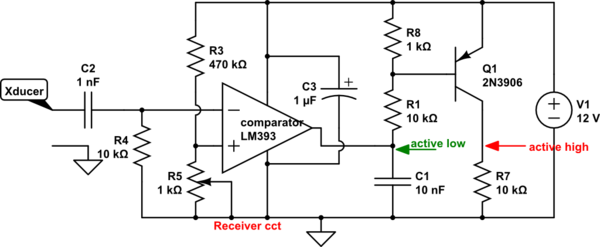
That simple transmitter circuit seems OK. You might reduce R1's value a tad.
Receiver circuit has problems.
A variable threshold level might be in order via R5 (1k trimpot) below. It is easiest to arrange the comparator so output pin goes low when input is excited with 40 kHz. Output is at +12V when idle: R1 (10k) is absolutely necessary as a pull-up to +12V.
A 1nf input capacitor high-pass input filter helps to keep audio from triggering...these ultrasonic transducers still have some response below 20kHz.

simulate this circuit – Schematic created using CircuitLab
