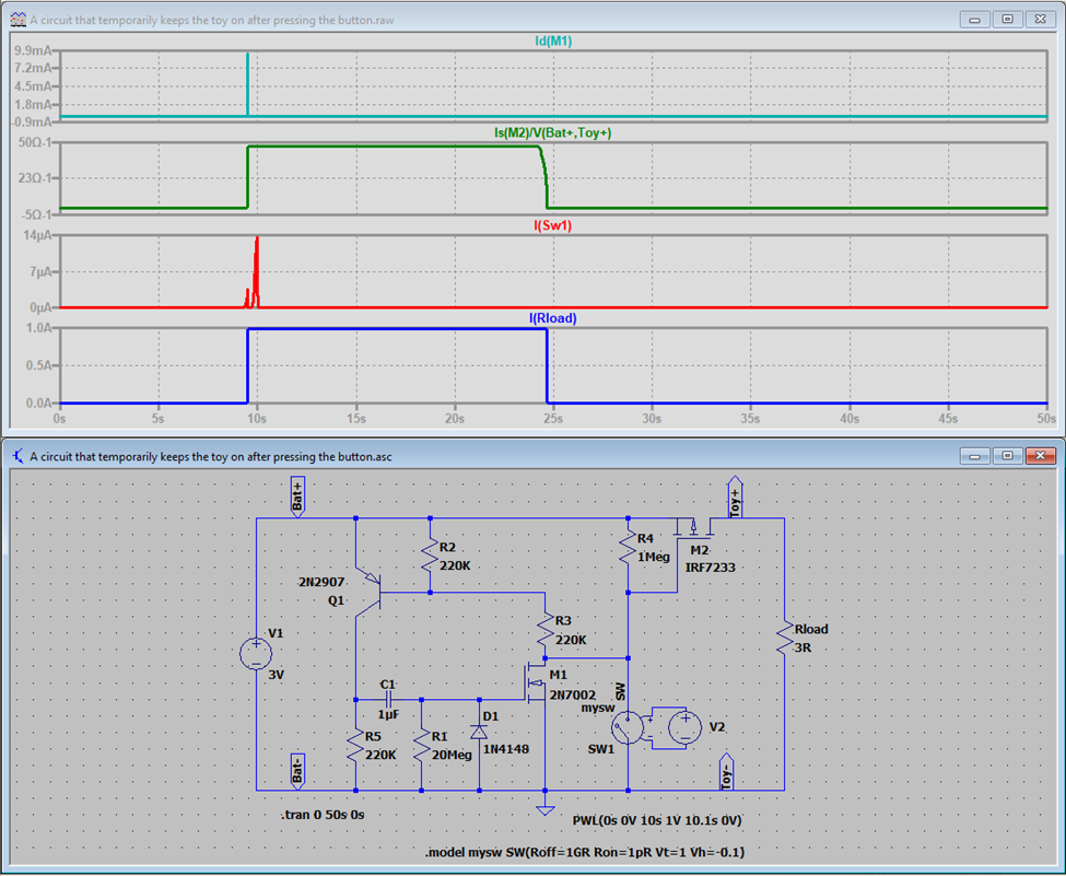
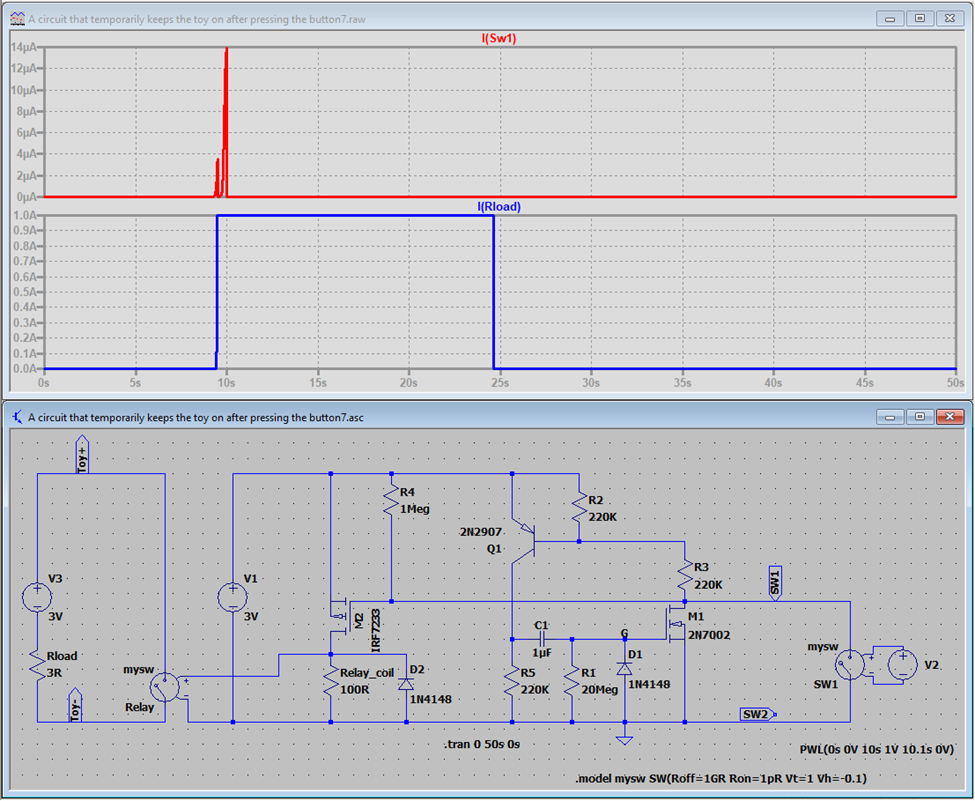
How about the circuit simulated below?
It comes from Figure 3.99D on page 196 of “The Art of Electronics Third Edition” by Paul Horowitz.
The time constant is controlled by R1 and C1, and it will be different for different battery voltages. You can change it by maintaining C1 and changing R1.
You will have to check the transistors (BJT and MOS) that you may have available and their characteristics (mainly the PMOS M2), as this will be the one you want with low RDS(on) so not to drop too much voltage from the battery to the toy.
I have used what the simulator had available. The 2N7002 can be the 2N7000 and Q1 can be any small signal transistor as it does not drain too much current.
I have eliminated the Zener diode because, for a battery of 3V or 4.5V (the original circuit used a 9V battery), I believed it was not necessary.
You can see that it is a compact configuration and you can build it as an extension cable between the battery and the toy.
Thanks.
EDIT:
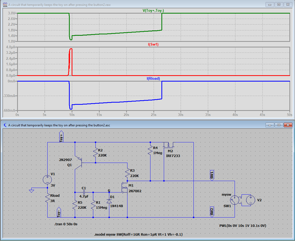
After some thought I realized that my answer does not correctly resolve your problem: The circuit has to be completely separated from the toy and the switch, resting in between them.
So, I have changed my circuit accordingly and have shown the simulation below even though, I know, the polarity of the circuit will still be an issue. To resolve that, you will have to have a connector between the toy and your circuit that can switch its terminals for the correct polarity. I have not considered any other solution for that, as any additional component in the circuit will increase the major problem I am indicating next (look at the Rload current in the chart below).
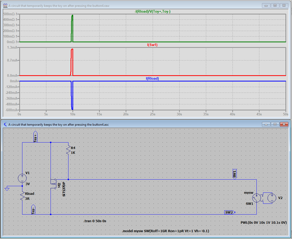
However, there is a much big problem here. Your circuit will not have the full power of the battery, as the load sits in between them. You just have a fraction of it. Any circuit you install in between them will have the same problem. That is shown in the simulation below where I have eliminated all the components but the PMOS that would drive the load. And that was a PMOS with an RDS(ON) of 2mR. As you can see, when the switch closes, you will only get 60% of the power.
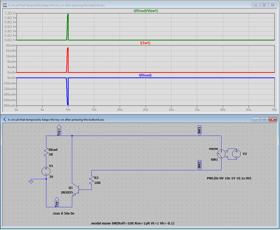
Even if you consider a BJT transistor, which drives more current than the PMOS as it has a lower ON resistance, you still won’t have the full power the toy needs as shown in the simulation below. This is the result of the impedance of the circuit, as shown in the green charts. In the PMOS it was 1/500mR = 2R and the BJT it is 1/1.2R = 0.8333R.
Even an SSR with an RDS(ON) of hundreds of milliohms will not give the toy a full power. Unless you use a RELAY (where the contacts do not depend on the polarity of the connection) and a separated battery (please see the simulation below), any solution will have to be between the battery and the load.
Thanks.

