We're talking about ideal sources. It's usually inappropriate to apply Ohm's law to them. Ohm's law applies to elements that have a very clear dependency between the voltage across and current through them, which is not the case for ideal sources.
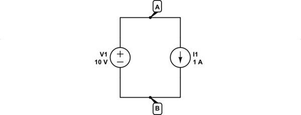
Perhaps the simplest demonstration of a source's independence of voltage and current is when we connect a current source in parallel with a voltage source:

simulate this circuit – Schematic created using CircuitLab
You might think that there's a conflict here, but there isn't. The only job of voltage source V1 is to apply a fixed potential difference of 10V between A and B. The only job of current source I1 is to ensure that 1A flows around the loop. Neither of those roles are in conflict with the other. Source V1 has no problem with I1's insistence that current be 1A, and source I1 has no problem with V1's insistence that the voltage across it be 10V.
The two sources behave as follows:
A voltage source always has a fixed potential difference across it, but will not impose any constraints on what current flows through it. The only thing it has to say about anything is what voltage is across it, having absolutely no control over current that flows. Issues of current are left up to other elements of the circuit.
A current source always has a fixed current through it, and has nothing to say about what voltage exists across it, and has no control over that voltage. It leaves all decisions regarding voltage up to the other elements in the circuit.
There's no ambiguity about the current, here, or the voltage, and either source can change what the conditions that it "imposes" without the other so much as batting an eyelid. In other words, where does resistance play a role here? No equations that you derive for the behaviour of this circuit make any mention of "resistance" at all. There are two equations:
$$ V = 10V $$ $$ I = 1A $$
That's it. Where's the R?
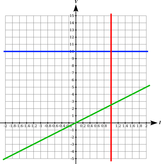
Let's look at the current vs. voltage curves for the voltage source (blue), current source (red) and a 2.5Ω resistance (green):
The voltage source's voltage (blue) remains fixed at 10V regardless of the current through it. By contrast, regardless of the voltage (red) across the current source, its current remains constant at 1A.
The key difference between those two graphs and the green (resistance) one is that the green trace passes through the origin (0, 0). This means that it obeys at all times the relationship:
$$ R = \frac{V}{I} = \frac{5}{2} = 2.5\Omega $$
Ohm's law therefore describes a direct proportionality between current and voltage, which results in 0V across a resistor when 0A passes through it. Both proportionality and passing through the origin are features missing from the sources' behaviours. Therefore it's not appropriate to apply Ohm's law to sources.
If you insist on assigning some kind of resistance value to a source, then you must first define what that resistance means. A practical definition of resistance in these circumstances goes as follows: resistance is the ratio of change in voltage to change in current:
$$ r = \frac{\Delta V}{\Delta I} $$
In mathematical treatments you will normally see the above relationship written:
$$ r = \frac{dV}{dI} $$
If you paid attention in math class, then you'll understand that this is referring to the gradient (slope) of the graph of \$V\$ vs. \$I\$, at some particular point \$(I, V)\$ on that graph. I've used a small \$r\$ to indicate that this is dynamic resistance, as distinct from ohmic, which applies only to resistors.
By that new definition, the dynamic resistance of a voltage source will be the gradient of its \$V\$ vs. \$I\$ plot, which is zero:
$$ r_{V1} = 0\Omega $$
The dynamic resistance of a current source is also the gradient of it's \$V\$ vs. \$I\$ plot:
$$ r_{I1} = \infty\Omega $$
The dynamic resistance of a resistor is the same as its ohmic resistance, because the gradient is constant, and proportionality is direct. For a resistor, Ohm's law is always true, for all values of \$V\$ and \$I\$, and both \$V\$ and \$I\$ are able to change:
$$ R = r = \frac{dV}{dI} = \frac{V}{I} $$
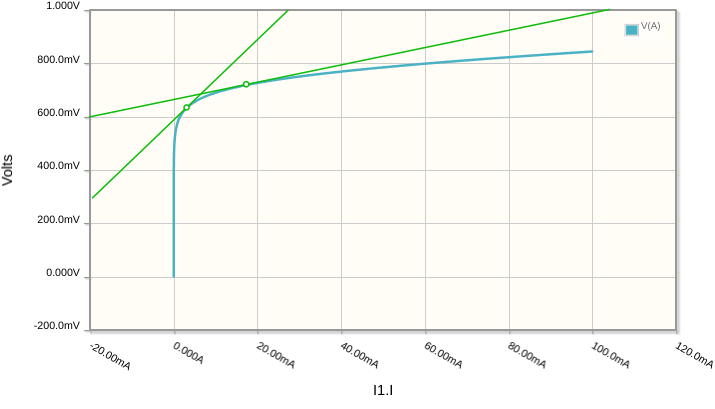
Dynamic resistance is a very useful concept. For any component that does not have a linear (straight line) \$V\$ vs. \$I\$ curve, the gradient of the curve changes as you vary either voltage or current. Take the silicon diode, for example. Its V-I curve is the blue line here:
The response of the diode to very small changes in current is different depending on where you "reside" on this graph, since the gradient of the curve is different everywhere. In other words, by passing an average (DC) current of 18mA through the diode, and making small ±100μA fluctuations (the "AC signal") , the resulting voltage changes across the diode will be much smaller than the changes you can expect if the average DC current through it were 3mA. This permits you to control gain.
To summarise, then, voltage sources produce fixed voltages and current sources provide fixed currents, but don't otherwise provide any level of control other than that.
The relationship between voltage and current is embodied by Ohm's law for resistors, and a variant of Ohm's law which deals with changes in voltage and current for everything else. (There are also formulae which deal with the relationship between voltage and current for inductors and capacitors, which introduce the variable time, but that's another topic altogether). With resistors, this relationship is called "resistance".
It is not appropriate to apply Ohm's law, and the concept of ohmic resistance, to a voltage source, or to a current source, because the relationship between voltage and current for them is not directly proportional.
You can, however, attribute to them the properties of dynamic resistance, when you consider their response to changes in either voltage or current. In that case an ideal voltage source can be considered to have zero resistance, and an ideal current source is considered to have infinite resistance.


