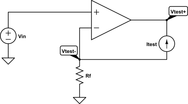
The output impedance of a two port network can be found by replacing the load resistor by a current source with known current \$I_\text{TEST} \$, calculating the voltage drop across it, and dividing the two. In this case it would look like this: -

simulate this circuit – Schematic created using CircuitLab
No current flows into the opamp terminals so \$V_\text{TEST-} = -I_\text{TEST}R_f \$. The output of the opamp is equal to the open loop gain \$A_0\$ multiplied by the voltage difference between the terminals, so $$V_\text{TEST,+} = A_0(V_\text{in}-V_\text{TEST-}) $$ Assuming that \$V_\text{in} \neq V_\text{TEST-}\$ we can without loss of generality set \$V_\text{in} = 0 \: \text{V} \$, causing
$$V_\text{TEST,+} = -A_0V_\text{TEST-} = A_0I_\text{TEST}R_f $$
The voltage drop across \$I_\text{TEST}\$ is
$$V_\text{TEST,+} - V_\text{TEST,-} = A_0I_\text{TEST}R_f - I_\text{TEST}R_f = I_\text{TEST}R_f(A_0-1)$$
Finally , the output impedance
$$Z_\text{out} = \frac{V_\text{TEST,+}-V_\text{TEST,-}}{I_\text{TEST}} = \frac{I_\text{TEST}R_f(A_0-1)}{I_\text{TEST}} $$
$$Z_\text{out} = {R_f(A_0-1)} $$ For an ideal opamp \$A_0 \to \infty\$ so clearly $$Z_\text{out} \to \infty $$
Two things to note here: First, is that the circuit is simply a non-inverting amplifier. The interesting part, is that the feedback resistor is considered as the load resistor \$R_L\$ which I haven't seen before. Secondly, in the analysis above note that the principle of a virtual short doesn't apply to the opamp's input terminals because the ideal current source determines the voltage across \$R_f\$ independently of everything else. In a general setting with a regular load resistance the virtual short principle will apply, however.
