added 234 characters in body
Source Link
Cloud
  • 830
  • 2
  • 12
  • 19

I have a Raspberry PI board connected to some external circuitry, and am using Microchip MCP23008 I2C GPIO expander chips to control external LEDs and motor circuitry. One important part of this external circuitry is a 12V buck-boost switching power supply which is powered off of a 9V battery. The buck-boost regulator does not have an enable pin, and I am working out a way to cut the power to the regulator.

I already have a working 9V low-battery indicator circuit (shown below), which turns on the green LED if the battery is supplying a voltage greater than 7.0V, and if the voltage dips below 7.0V, the red LED is enabled. The circuit should also cut off the current coming out of the source of Q4.
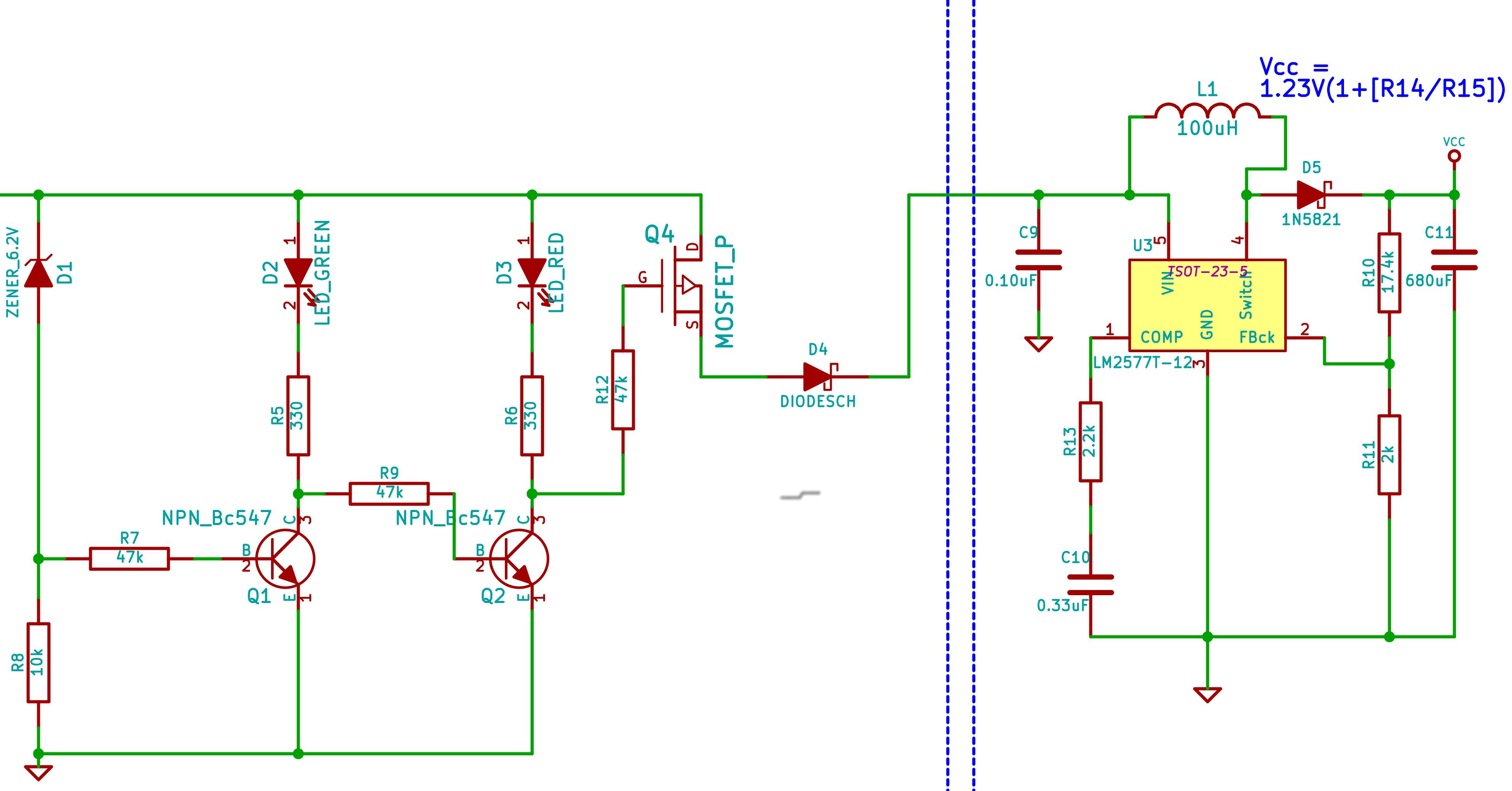

Circuit - Version 1

Device Under Test (DUT)


I have two questions with respect to this circuit:

First, does the cutoff logic make sense? My assumption is that if the red LED is off, no current is going through D3, R6, and Q2, so the voltage at the node between R6 and the collector of Q2 would be the same as the power rail connected at the top to D1, D2, D3, and Q4's drain. If the red LED is on, there's a 0.7V drop across it, then a moderate drop across R6 (ie: estimated current, (7.0V-0.7V) / 330R = 19mA, so a 6.27V drop across the resistor roughly), and since this will make the Q4 bias less than that connected to Q4's drain, Q4 is turned off, cutting off power to the buck-boost converter. I'm convinced I'm overlooking V_ce on Q2 though.

Second, is it safe to assume the regulator can run from the output of the source of Q4 and D4? My estimates suggest that I will, when drawing current, have a 0.2V drop (V_ds) across Q4, and another 0.3V drop across D4.


Edit: Adding updated circuit as per earlier suggestions.
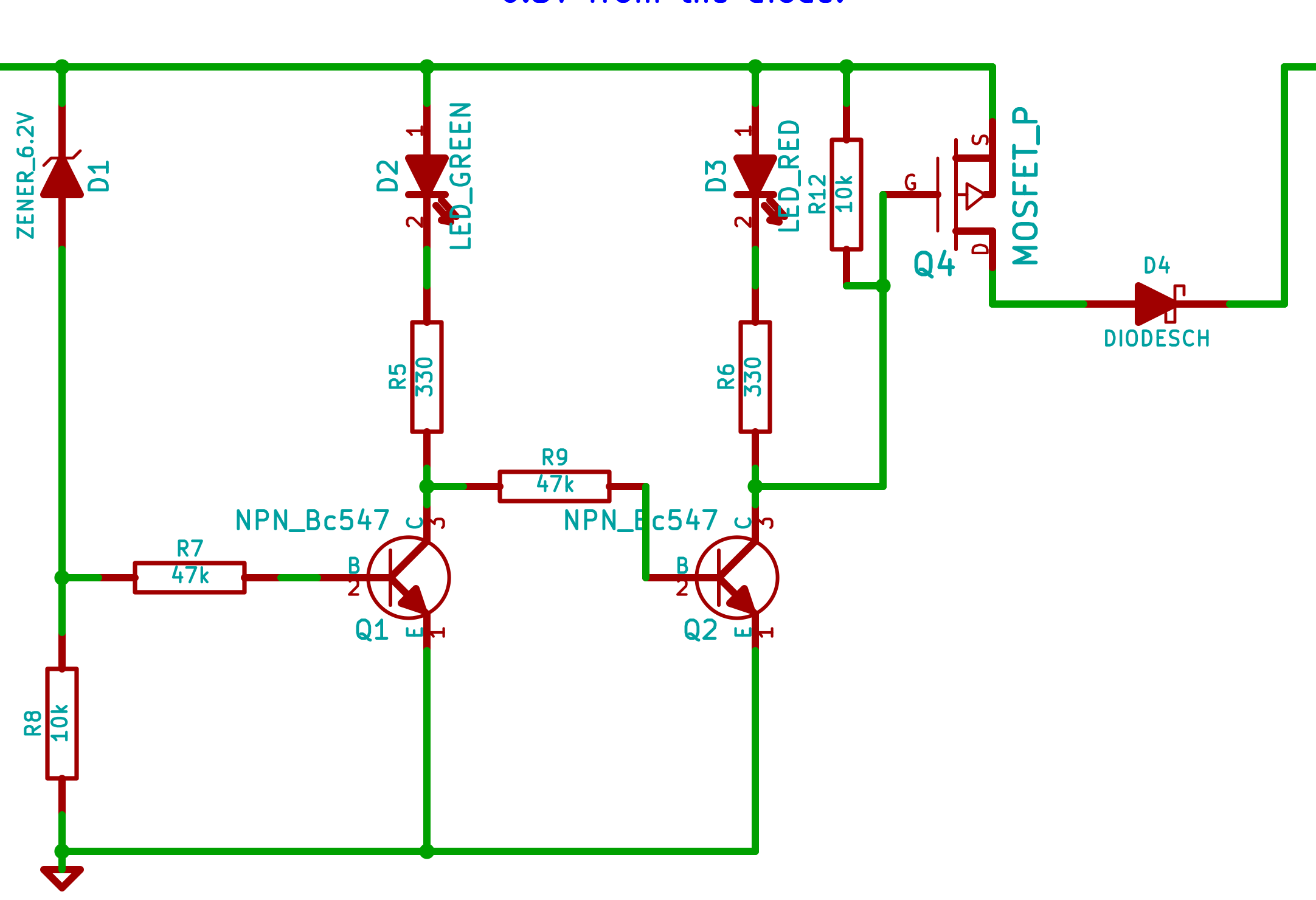
Circuit - Version 2

Device Under Test (DUT)


Edit 2: Updating as per latest answers.

I updated the circuit to reflect that of the answer provided by @DanLaks. Attaching DC sweep simulation.
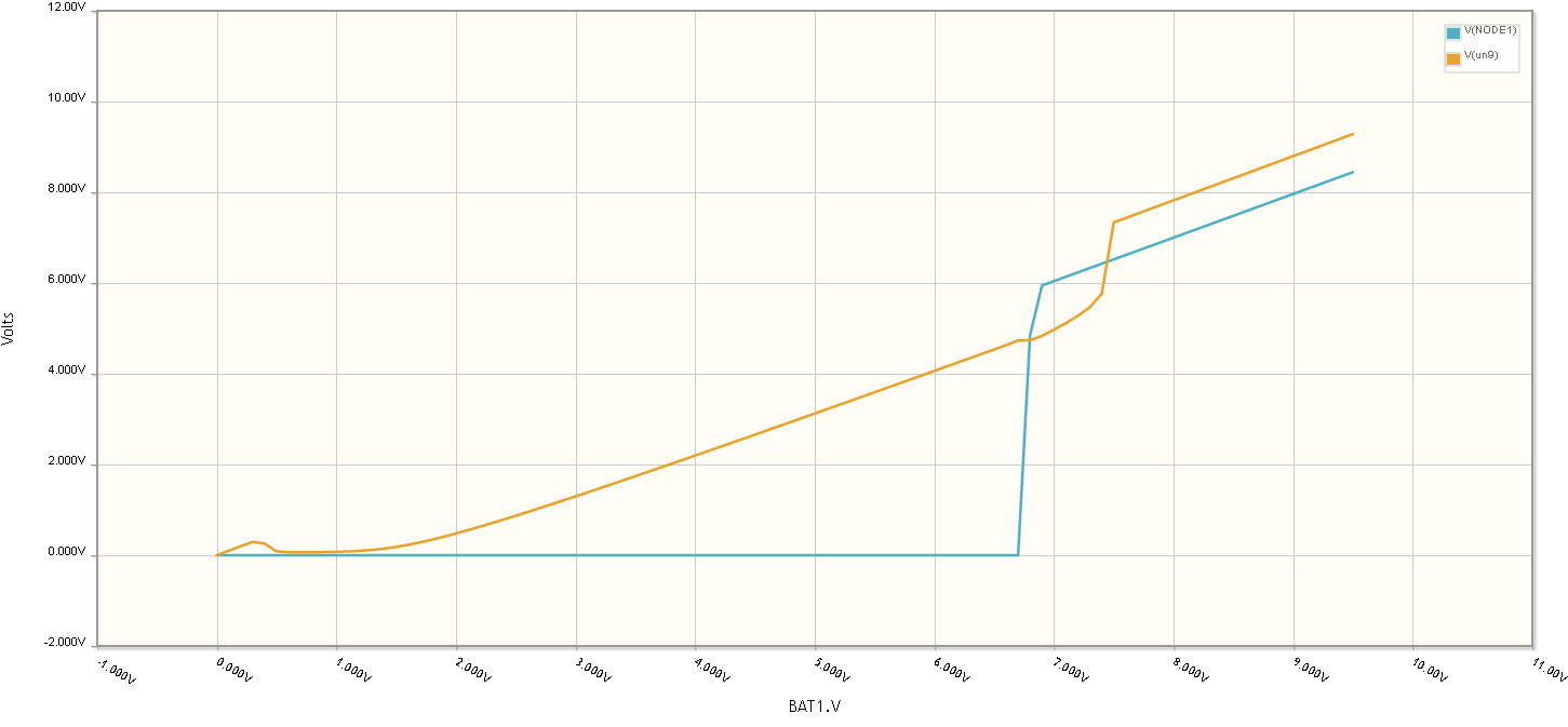
DC Sweep Simulation


I have a Raspberry PI board connected to some external circuitry, and am using Microchip MCP23008 I2C GPIO expander chips to control external LEDs and motor circuitry. One important part of this external circuitry is a 12V buck-boost switching power supply which is powered off of a 9V battery. The buck-boost regulator does not have an enable pin, and I am working out a way to cut the power to the regulator.

I already have a working 9V low-battery indicator circuit (shown below), which turns on the green LED if the battery is supplying a voltage greater than 7.0V, and if the voltage dips below 7.0V, the red LED is enabled. The circuit should also cut off the current coming out of the source of Q4.


Circuit - Version 1

Device Under Test (DUT)


I have two questions with respect to this circuit:

First, does the cutoff logic make sense? My assumption is that if the red LED is off, no current is going through D3, R6, and Q2, so the voltage at the node between R6 and the collector of Q2 would be the same as the power rail connected at the top to D1, D2, D3, and Q4's drain. If the red LED is on, there's a 0.7V drop across it, then a moderate drop across R6 (ie: estimated current, (7.0V-0.7V) / 330R = 19mA, so a 6.27V drop across the resistor roughly), and since this will make the Q4 bias less than that connected to Q4's drain, Q4 is turned off, cutting off power to the buck-boost converter. I'm convinced I'm overlooking V_ce on Q2 though.

Second, is it safe to assume the regulator can run from the output of the source of Q4 and D4? My estimates suggest that I will, when drawing current, have a 0.2V drop (V_ds) across Q4, and another 0.3V drop across D4.


Edit: Adding updated circuit as per earlier suggestions.

Circuit - Version 2

Device Under Test (DUT)


Edit 2: Updating as per latest answers.

I updated the circuit to reflect that of the answer provided by @DanLaks. Attaching DC sweep simulation.

DC Sweep Simulation


added 229 characters in body
Source Link
Cloud
  • 830
  • 2
  • 12
  • 19

I have a Raspberry PI board connected to some external circuitry, and am using Microchip MCP23008 I2C GPIO expander chips to control external LEDs and motor circuitry. One important part of this external circuitry is a 12V buck-boost switching power supply which is powered off of a 9V battery. The buck-boost regulator does not have an enable pin, and I am working out a way to cut the power to the regulator.

I already have a working 9V low-battery indicator circuit (shown below), which turns on the green LED if the battery is supplying a voltage greater than 7.0V, and if the voltage dips below 7.0V, the red LED is enabled. The circuit should also cut off the current coming out of the source of Q4.


Circuit - Version 1

Device Under Test (DUT)


I have two questions with respect to this circuit:

First, does the cutoff logic make sense? My assumption is that if the red LED is off, no current is going through D3, R6, and Q2, so the voltage at the node between R6 and the collector of Q2 would be the same as the power rail connected at the top to D1, D2, D3, and Q4's drain. If the red LED is on, there's a 0.7V drop across it, then a moderate drop across R6 (ie: estimated current, (7.0V-0.7V) / 330R = 19mA, so a 6.27V drop across the resistor roughly), and since this will make the Q4 bias less than that connected to Q4's drain, Q4 is turned off, cutting off power to the buck-boost converter. I'm convinced I'm overlooking V_ce on Q2 though.

Second, is it safe to assume the regulator can run from the output of the source of Q4 and D4? My estimates suggest that I will, when drawing current, have a 0.2V drop (V_ds) across Q4, and another 0.3V drop across D4.


Edit: Adding updated circuit as per earlier suggestions.

Circuit - Version 2

Device Under Test (DUT)


I have a Raspberry PI board connected to some external circuitry, and am using Microchip MCP23008 I2C GPIO expander chips to control external LEDs and motor circuitry. One important part of this external circuitry is a 12V buck-boost switching power supply which is powered off of a 9V battery. The buck-boost regulator does not have an enable pin, and I am working out a way to cut the power to the regulator.

I already have a working 9V low-battery indicator circuit (shown below), which turns on the green LED if the battery is supplying a voltage greater than 7.0V, and if the voltage dips below 7.0V, the red LED is enabled. The circuit should also cut off the current coming out of the source of Q4.


Circuit - Version 1

Device Under Test (DUT)


I have two questions with respect to this circuit:

First, does the cutoff logic make sense? My assumption is that if the red LED is off, no current is going through D3, R6, and Q2, so the voltage at the node between R6 and the collector of Q2 would be the same as the power rail connected at the top to D1, D2, D3, and Q4's drain. If the red LED is on, there's a 0.7V drop across it, then a moderate drop across R6 (ie: estimated current, (7.0V-0.7V) / 330R = 19mA, so a 6.27V drop across the resistor roughly), and since this will make the Q4 bias less than that connected to Q4's drain, Q4 is turned off, cutting off power to the buck-boost converter. I'm convinced I'm overlooking V_ce on Q2 though.

Second, is it safe to assume the regulator can run from the output of the source of Q4 and D4? My estimates suggest that I will, when drawing current, have a 0.2V drop (V_ds) across Q4, and another 0.3V drop across D4.


Edit: Adding updated circuit as per earlier suggestions.

Circuit - Version 2

Device Under Test (DUT)


added 89 characters in body
Source Link
Cloud
  • 830
  • 2
  • 12
  • 19

I have a Raspberry PI board connected to some external circuitry, and am using Microchip MCP23008 I2C GPIO expander chips to control external LEDs and motor circuitry. One important part of this external circuitry is a 12V buck-boost switching power supply which is powered off of a 9V battery. The buck-boost regulator does not have an enable pin, and I am working out a way to cut the power to the regulator.

I already have a working 9V low-battery indicator circuit (shown below), which turns on the green LED if the battery is supplying a voltage greater than 7.0V, and if the voltage dips below 7.0V, the red LED is enabled. The circuit should also cut off the current coming out of the source of Q4.


Circuit - Version 1

Device Under Test (DUT)


I have two questions with respect to this circuit:

First, does the cutoff logic make sense? My assumption is that if the red LED is off, no current is going through D3, R6, and Q2, so the voltage at the node between R6 and the collector of Q2 would be the same as the power rail connected at the top to D1, D2, D3, and Q4's drain. If the red LED is on, there's a 0.7V drop across it, then a moderate drop across R6 (ie: estimated current, (7.0V-0.7V) / 330R = 19mA, so a 6.27V drop across the resistor roughly), and since this will make the Q4 bias less than that connected to Q4's drain, Q4 is turned off, cutting off power to the buck-boost converter. I'm convinced I'm overlooking V_ce on Q2 though.

Second, is it safe to assume the regulator can run from the output of the source of Q4 and D4? My estimates suggest that I will, when drawing current, have a 0.2V drop (V_ds) across Q4, and another 0.3V drop across D4.

I have a Raspberry PI board connected to some external circuitry, and am using Microchip MCP23008 I2C GPIO expander chips to control external LEDs and motor circuitry. One important part of this external circuitry is a 12V buck-boost switching power supply which is powered off of a 9V battery. The buck-boost regulator does not have an enable pin, and I am working out a way to cut the power to the regulator.

I already have a working 9V low-battery indicator circuit (shown below), which turns on the green LED if the battery is supplying a voltage greater than 7.0V, and if the voltage dips below 7.0V, the red LED is enabled. The circuit should also cut off the current coming out of the source of Q4.

Device Under Test (DUT)

I have two questions with respect to this circuit:

First, does the cutoff logic make sense? My assumption is that if the red LED is off, no current is going through D3, R6, and Q2, so the voltage at the node between R6 and the collector of Q2 would be the same as the power rail connected at the top to D1, D2, D3, and Q4's drain. If the red LED is on, there's a 0.7V drop across it, then a moderate drop across R6 (ie: estimated current, (7.0V-0.7V) / 330R = 19mA, so a 6.27V drop across the resistor roughly), and since this will make the Q4 bias less than that connected to Q4's drain, Q4 is turned off, cutting off power to the buck-boost converter. I'm convinced I'm overlooking V_ce on Q2 though.

Second, is it safe to assume the regulator can run from the output of the source of Q4 and D4? My estimates suggest that I will, when drawing current, have a 0.2V drop (V_ds) across Q4, and another 0.3V drop across D4.

I have a Raspberry PI board connected to some external circuitry, and am using Microchip MCP23008 I2C GPIO expander chips to control external LEDs and motor circuitry. One important part of this external circuitry is a 12V buck-boost switching power supply which is powered off of a 9V battery. The buck-boost regulator does not have an enable pin, and I am working out a way to cut the power to the regulator.

I already have a working 9V low-battery indicator circuit (shown below), which turns on the green LED if the battery is supplying a voltage greater than 7.0V, and if the voltage dips below 7.0V, the red LED is enabled. The circuit should also cut off the current coming out of the source of Q4.


Circuit - Version 1

Device Under Test (DUT)


I have two questions with respect to this circuit:

First, does the cutoff logic make sense? My assumption is that if the red LED is off, no current is going through D3, R6, and Q2, so the voltage at the node between R6 and the collector of Q2 would be the same as the power rail connected at the top to D1, D2, D3, and Q4's drain. If the red LED is on, there's a 0.7V drop across it, then a moderate drop across R6 (ie: estimated current, (7.0V-0.7V) / 330R = 19mA, so a 6.27V drop across the resistor roughly), and since this will make the Q4 bias less than that connected to Q4's drain, Q4 is turned off, cutting off power to the buck-boost converter. I'm convinced I'm overlooking V_ce on Q2 though.

Second, is it safe to assume the regulator can run from the output of the source of Q4 and D4? My estimates suggest that I will, when drawing current, have a 0.2V drop (V_ds) across Q4, and another 0.3V drop across D4.

Source Link
Cloud
  • 830
  • 2
  • 12
  • 19
Loading