added 43 characters in body
Source Link
John Alawi
  • 55
  • 3
  • 11

how to step down the voltage from 100V(after a FullWaverectifier) to 1V without efectingaffected by noise

howHow to step down the voltage from 100V(after a Full Wave rectifier) to 1V without effectedaffected by the noise?

The task

I have 70Vrms sine wave, I rectified it with full wave rectifier. So the output is 100Vp.
I will divide it down to 1V using voltage divider (0-100V to 0-1V). How could I add a 1.4V DC bias to the output of the voltage divided ?

Briefly: $$ 70V_\text{rms} \Longrightarrow 0-100V_\text{p} \Longrightarrow 0-1V \Longrightarrow 1.4-2.4V$$

  • I have a 5V DC I could used it in the biasing

The solution I used enter image description here
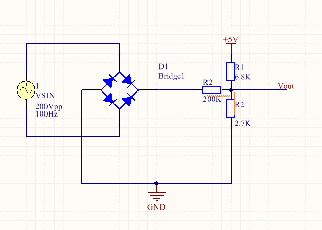
I try with voltage divider and I had a lot of noise since 10V inwill give my 0.1Vout1 Vout.

enter image description here

Here is my projectHere is my project enter image description here

When the voltage is 56Vrms, I get the following results ( the green is the signal at PWM pin1 and the yellow is at R6 -the AM demodulator- ) enter image description here
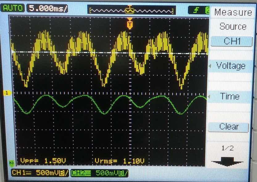
The voltage at pin 1 of the PWM IC (UC3526AN) have to be 1.4VDC bias with 1Vpp when tethe input voltage is 100Vpp but it is not. The following is the real measurements at pin 1.

The results and the problems

  • At about 20Vrms input enter image description here
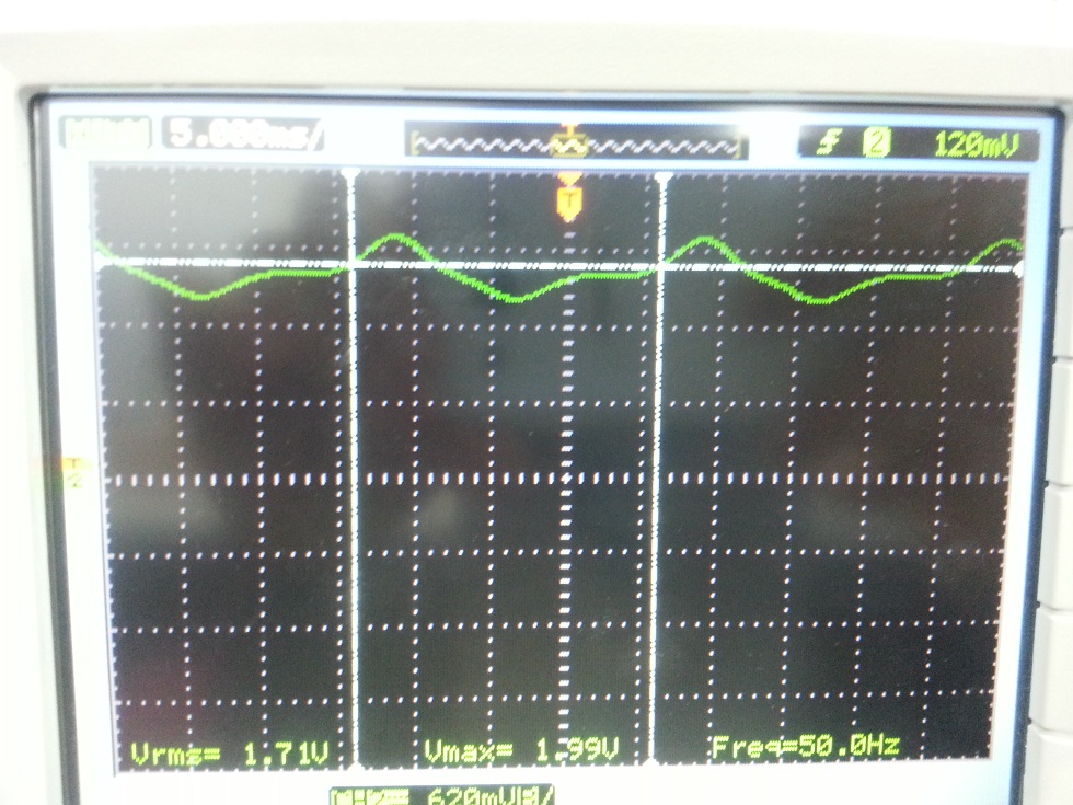
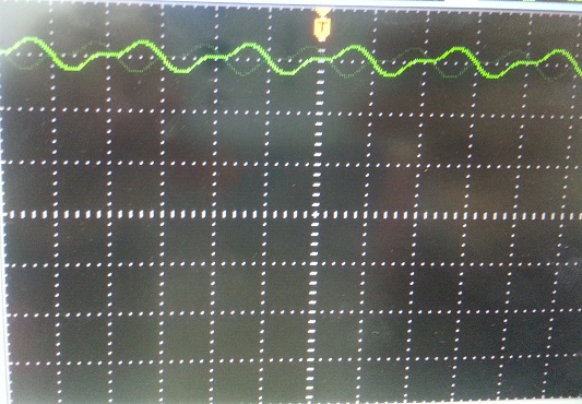
  • At about 30Vrms input enter image description here
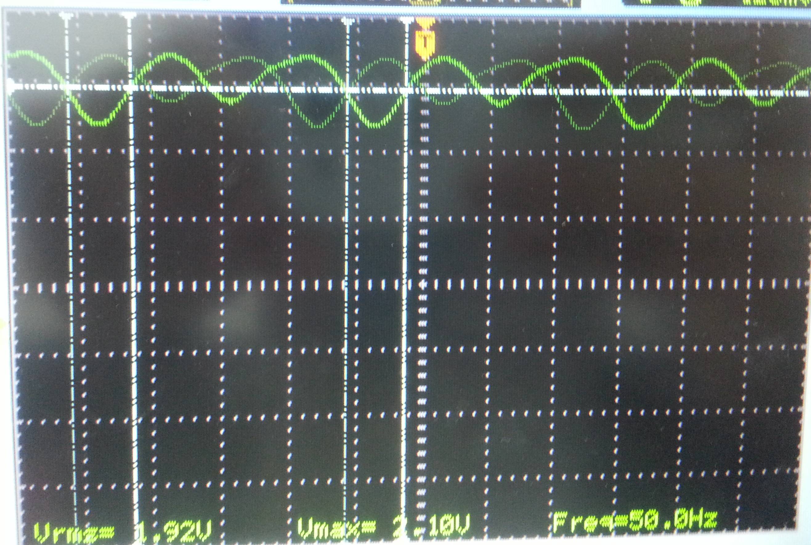
  • At about 68Vrms input enter image description here
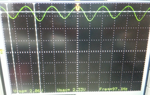
  • At about 100Vrms input enter image description here

how to step down the voltage from 100V(after a FullWaverectifier) to 1V without efecting by noise

how to step down the voltage from 100V(after a Full Wave rectifier) to 1V without effected by the noise?

I try with voltage divider and I had a lot of noise since 10V in give my 0.1Vout.

enter image description here

Here is my project enter image description here

When the voltage is 56Vrms, I get the following results ( the green is the signal at PWM pin1 and the yellow is at R6 -the AM demodulator- ) enter image description here

The voltage at pin 1 of the PWM IC (UC3526AN) have to be 1.4VDC bias with 1Vpp when te input voltage is 100Vpp but it is not. The following is the real measurements at pin 1.

  • At about 20Vrms input enter image description here
  • At about 30Vrms input enter image description here
  • At about 68Vrms input enter image description here
  • At about 100Vrms input enter image description here

how to step down the voltage from 100V(after a FullWaverectifier) to 1V without affected by noise

How to step down the voltage from 100V(after a Full Wave rectifier) to 1V without affected by the noise?

The task

I have 70Vrms sine wave, I rectified it with full wave rectifier. So the output is 100Vp.
I will divide it down to 1V using voltage divider (0-100V to 0-1V). How could I add a 1.4V DC bias to the output of the voltage divided ?

Briefly: $$ 70V_\text{rms} \Longrightarrow 0-100V_\text{p} \Longrightarrow 0-1V \Longrightarrow 1.4-2.4V$$

  • I have a 5V DC I could used it in the biasing

The solution I used enter image description here

I try with voltage divider and I had a lot of noise since 10V will give my 0.1 Vout.

Here is my project enter image description here

When the voltage is 56Vrms, I get the following results ( the green is the signal at PWM pin1 and the yellow is at R6 -the AM demodulator- ) enter image description here

The voltage at pin 1 of the PWM IC (UC3526AN) have to be 1.4VDC bias with 1Vpp when the input voltage is 100Vpp but it is not. The following is the real measurements at pin 1.

The results and the problems

  • At about 20Vrms input enter image description here
  • At about 30Vrms input enter image description here
  • At about 68Vrms input enter image description here
  • At about 100Vrms input enter image description here
added 43 characters in body
Source Link
John Alawi
  • 55
  • 3
  • 11

how to step down the voltage from 100V(after a Full Wave rectifier) to 1V without effected by the noise?

I try with voltage divider and I had a lot of noise since 10V in give my 0.1Vout.

enter image description here

Here is my project enter image description here

When the voltage is 56Vrms, I get the following results ( the green is the signal at PWM pin1 and the yellow is at R6 -the AM demodulator- ) enter image description here

The voltage at pin 1 of the PWM IC (UC3526AN) have to be 1.4VDC bias with 1Vpp when te input voltage is 100Vpp but it is not. The following is the real measurements at pin 1.

  • At about 20Vrms input enter image description here
  • At about 30Vrms input enter image description here
  • At about 68Vrms input enter image description here
  • At about 100Vrms input enter image description here
added 934 characters in body
Source Link
John Alawi
  • 55
  • 3
  • 11

how to step down the voltage from 100V(after a Full Wave rectifier) to 1V without effected by the noise?

I try with voltage divider and I had aloa lot of noise since 10V in give my 0.1Vout.

enter image description here

Here is my project enter image description here

When the voltage is 56Vrms, I get the following results ( the green is the signal at PWM pin1 and the yellow is at R6 -the AM demodulator- ) enter image description here

The voltage at pin 1 of the PWM IC (UC3526AN) have to be 1.4VDC bias with 1Vpp when te input voltage is 100Vpp but it is not. The following is the real measurements at pin 1.

  • At about 20Vrms input enter image description here
  • At about 30Vrms input enter image description here
  • At about 68Vrms input enter image description here
  • At about 100Vrms input enter image description here

how to step down the voltage from 100V(after a Full Wave rectifier) to 1V without effected by the noise?

I try with voltage divider and I had alo of noise since 10V in give my 0.1Vout.

enter image description here

how to step down the voltage from 100V(after a Full Wave rectifier) to 1V without effected by the noise?

I try with voltage divider and I had a lot of noise since 10V in give my 0.1Vout.

enter image description here

Here is my project enter image description here

When the voltage is 56Vrms, I get the following results ( the green is the signal at PWM pin1 and the yellow is at R6 -the AM demodulator- ) enter image description here

The voltage at pin 1 of the PWM IC (UC3526AN) have to be 1.4VDC bias with 1Vpp when te input voltage is 100Vpp but it is not. The following is the real measurements at pin 1.

  • At about 20Vrms input enter image description here
  • At about 30Vrms input enter image description here
  • At about 68Vrms input enter image description here
  • At about 100Vrms input enter image description here
Source Link
John Alawi
  • 55
  • 3
  • 11
Loading