0
\$\begingroup\$

How to step down the voltage from 100V(after a Full Wave rectifier) to 1V without affected by the noise?

The task

I have 70Vrms sine wave, I rectified it with full wave rectifier. So the output is 100Vp.
I will divide it down to 1V using voltage divider (0-100V to 0-1V). How could I add a 1.4V DC bias to the output of the voltage divided ?

Briefly: $$ 70V_\text{rms} \Longrightarrow 0-100V_\text{p} \Longrightarrow 0-1V \Longrightarrow 1.4-2.4V$$

  • I have a 5V DC I could used it in the biasing

The solution I used enter image description here
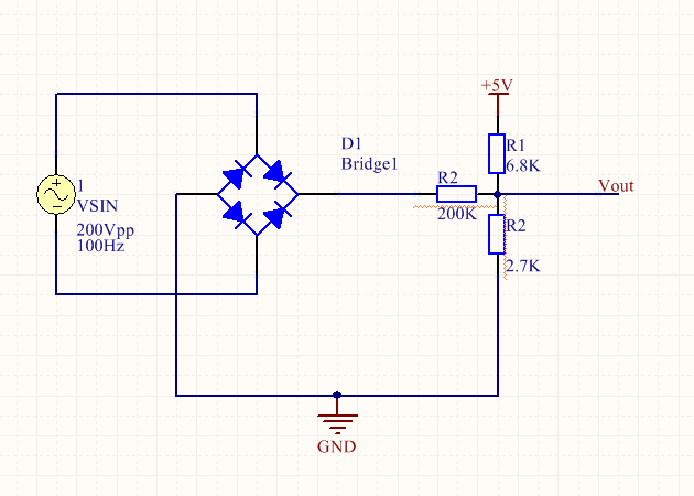
I try with voltage divider and I had a lot of noise since 10V will give my 0.1 Vout.

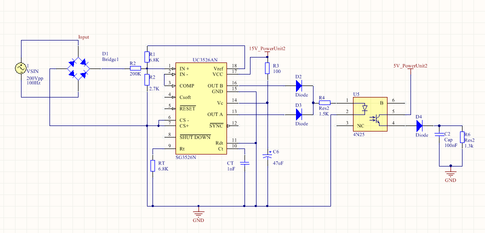
Here is my project enter image description here
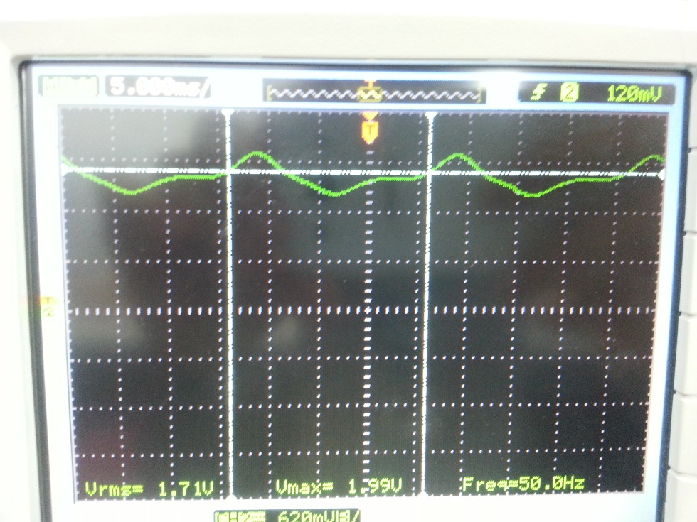
When the voltage is 56Vrms, I get the following results ( the green is the signal at PWM pin1 and the yellow is at R6 -the AM demodulator- ) enter image description here
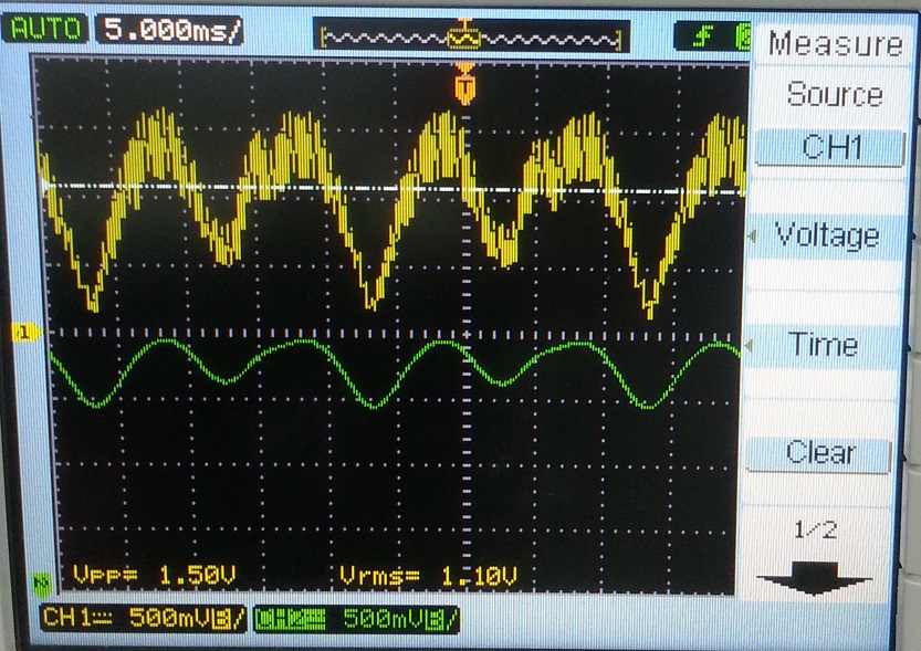
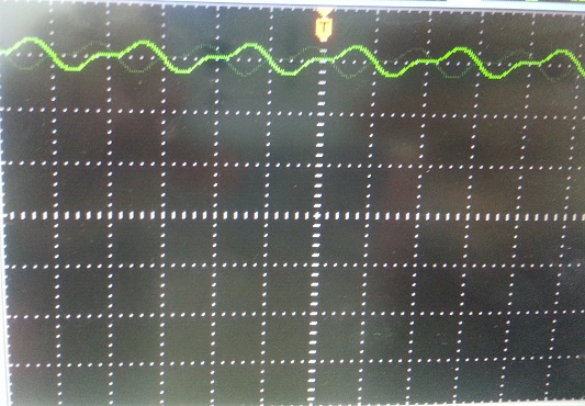
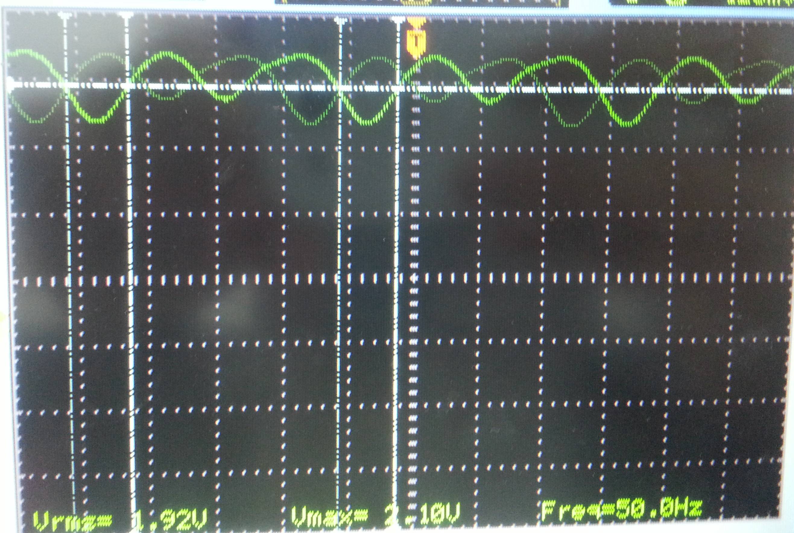
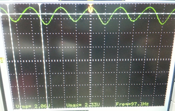
The voltage at pin 1 of the PWM IC (UC3526AN) have to be 1.4VDC bias with 1Vpp when the input voltage is 100Vpp but it is not. The following is the real measurements at pin 1.

The results and the problems

  • At about 20Vrms input enter image description here
  • At about 30Vrms input enter image description here
  • At about 68Vrms input enter image description here
  • At about 100Vrms input enter image description here
\$\endgroup\$
5
  • \$\begingroup\$ One would normally use a transformer, full-wave rectifier and a voltage regulator. \$\endgroup\$
    – Golaž
    Commented Apr 27, 2015 at 18:05
  • \$\begingroup\$ It's unclear what you expect to achieve by what you did. Try giving more detail of what you want. \$\endgroup\$
    – Andy aka
    Commented Apr 27, 2015 at 18:14
  • \$\begingroup\$ @Andyaka I add more information. \$\endgroup\$
    – John Alawi
    Commented Apr 27, 2015 at 18:37
  • \$\begingroup\$ @Golaž I am measuring the voltage using NI CompactDAQ and need to read it as it is after the bridge without any changes(no smoothing capacitor or voltage regulator ) \$\endgroup\$
    – John Alawi
    Commented Apr 27, 2015 at 18:39
  • \$\begingroup\$ All I see are results (scope pics). What are the problems? \$\endgroup\$
    – brhans
    Commented Apr 28, 2015 at 12:38

1 Answer 1

1
\$\begingroup\$

Step 1. remove R1 (pin 1 & GND)and R2 (2.7K) form 5V ref. supply 2. Remove the rectifier ground. 2. connect approx. 1.2 K res. between negative of rectified supply and ground. 3. connect approx. 3.3 K between 1.2 K and 5V ref.(u may have to fiddle with to get exact 1.4 V) 4. pref. connect 100 micro cap. across 1.2 K res. 5. and try VTIgole

\$\endgroup\$

Your Answer

By clicking “Post Your Answer”, you agree to our terms of service and acknowledge you have read our privacy policy.

Not the answer you're looking for? Browse other questions tagged or ask your own question.