##EDIT##NOTICE: For##
When first posting this answer, the umpteenth time CircuitLab has jiffered upstory was in most respects exactly the images. Now my post, as I see itsame, makes little to no sensebut a CircuitLab/Stack interaction or glitch effectively removed the middle bit. I need to leave for homehave now (already 20:50/8:50PM here)completely rewritten and that'll take a whileredrawn that. If someone wants to stealI hope the idea and post their own answer, or fix mine, you're welcomestory line is still sufficiently there, elsesince there was a 2 hour gap between the moments I will fix it when I'm home while dinner is cooking##had time to write.


simulate this circuitsimulate this circuit – Schematic created using CircuitLab
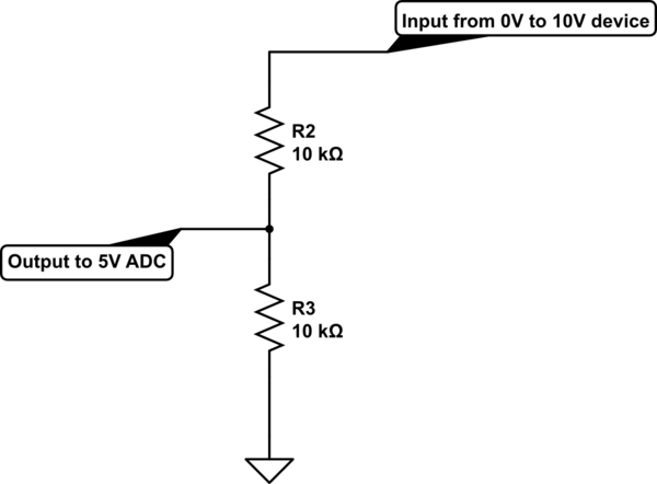
Here the resistors stack up to 20kOhm together, so if the input is 10V (maximum) the resistors will pull I = V / R = 10V / 20000Ohm = 0.5mA out of the measuring device. The I = V/R is called Ohm's law. Also written as V = I*R and R = V/I.
Now that current, if the device can supply it will go through the bottom resistor, where we are measuring and it will induce a voltage: V = I*R = 0.5mA * 10kOhm = 5V, which is exactly what we want.
I leave it to the reader to verify that as drawn, the output will be exactly half the input voltage for each voltage applied.
There is two important things though:
- The ADC that you use should have a high input impedance (>100kOhm, preferably >1MOhm), for the Atmel/Arduino, that is satisfied. - But if you switch ADC channels quickly with the Atmel, give it a few microseconds time between changing channels and assuming the data is right.
- You need to be sure the voltage is never more than 10V.
If you aren't sure about that last one, or you think "better safe than sorry", you can make this modification:

simulate this circuit
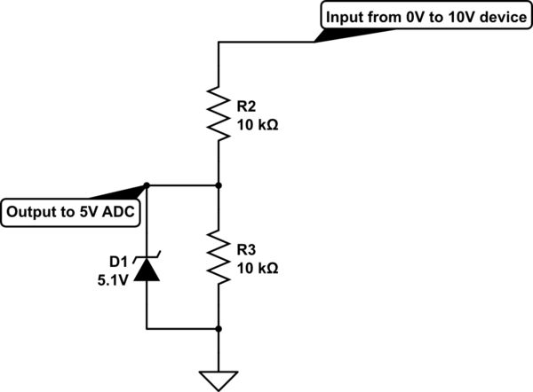
Now there is a zener diode on the output, if the input tries to go to 12V, in stead of the output just becomming 6V, the zener will drain some current, to try and keep it at its specified voltage.
If the zener diode is a perfect zener diode, that would be great. In theory a perfect zener exists and starts conducting at 5.10000000001V and then also conducts infinite current, but conducts nothing at 5.09999999999V. Of course, reality is different.
A zener diode will start conducting a little bit below its specified voltage, stealing some of the current away that should make the measurement voltage across the bottom resistor. So at higher output voltages (say above 4V) the response will no longer be exactly divide by two, but it will be a very slightly bent curve.
The effect can negligible if you use a small-signal zener, with its zener voltage defined at 1mA or 2mA.
End of the power-less (and very simple) designs, start of some more fancy tricks to be added on
((if nothing of the conditions above worries you, you can stop reading here if you fear you might fall asleep reading all this))
Now, there could be another question: What if the measurement device can't source 0.5mA? Or what if I don't know if it can? What if the device has a high output impedance, effectively adding another 2k or even 10k resistor, completely messing up the maths?
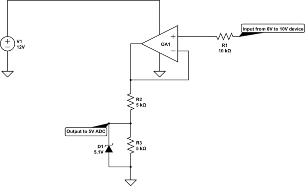
You could add an op-amp, if you also have a higher voltage supply, such as a 12V driving the Arduino (since that automatically also shares the ground with its internal 5V). Or a separate 15V adaptor, as long as it is a couple of volts above your input signal's maximum voltage. Only make sure that the supply voltage is below the maximum specified for your op-amp:

simulate this circuit
The op-amp I added just buffers the signal, nothing else. It tries to get the same voltage on its - input as on its + input, when there is negative feedback, which connecting the output back to - is. So if the +input becomes 6V, the op-amp wants to get 6V on the - input as well, the only way it can do that is by making the output 6V. So too for any other voltage in its range.
I have decreased the resistors, because we can expect a modern op-amp to be able to source 1mA with a 2V higher supply than its desired output or input levels. If the supply is at least 4V higher (in this case >= 14VDC) it should always be able to source that in mid to low frequencies and most still at quite high frequencies (that the Atmel can't capture anyway).
For this to work nearly perfectly at the 0V end you would need a rail-to-rail Op-Amp (they can be found by that name easy enough), but. But if you don't mind the lower 1V input range (lowest 10%) being distorted you can easily try with a normal one, like the LM358 and see if it can handle your requirements well enough.
The extra resistor (R1) isn't absolutely necessary, I just added it as a "in case the device at switch-on does something silly". If it does very silly stuff the op-amp might still not like it, but at least in this set-up it's much more likely your Arduino will survive it.
More ways to protect input and output
((yet more blabber))
Of course there are many other ways to handle input safety, you could add another zener diode valued at 11V12V on the op-amp's + pin, if you like, for example, but I suspect that's moving into the overkill domain.
You can use the Diode and the Zener both, but it should be sufficient to choose one.
##More buffering##
((With two op-amps you get twice the cool, easily!))


