##EDIT: For the umpteenth time CircuitLab has jiffered up the images. Now my post, as I see it, makes little to no sense. I need to leave for home now (already 20:50/8:50PM here) and that'll take a while. If someone wants to steal the idea and post their own answer, or fix mine, you're welcome, else I will fix it when I'm home while dinner is cooking##
No, you cannot connect them directly.
As you can see in your table all the signals go from 0 to 10V. Your Arduino (or, better: the Atmel inside it) can only work with signals up to a maximum of its supply voltage. Anything higher can damage it.
So, you need to attenuate the signal, so to speak, into something suitable. I am assuming you are using an Arduino on 5V, so take that into account if you are using it at a different voltage. (I will try to "show my workings" as much as possible).
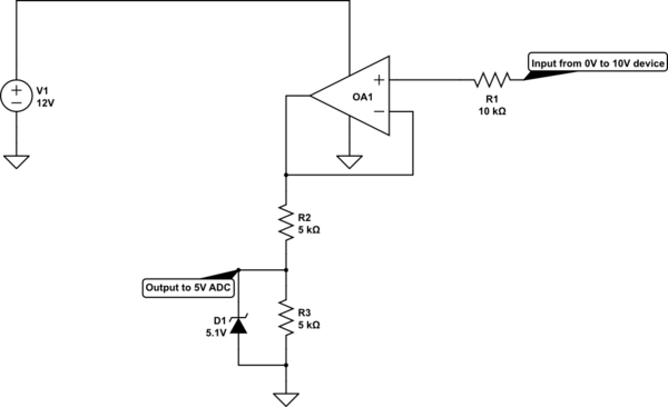
The simplest way would be:

simulate this circuit – Schematic created using CircuitLab
I have decreased the resistors, because we can expect a modern op-amp to be able to source 1mA with a 2V higher supply than its desired output or input levels. If the supply is at least 4V higher (in this case >= 14VDC) it should always be able to source that in mid to low frequencies and most still at quite high frequencies (that the Atmel can't capture anyway).
1mA gives a better response with the same zener than 0.5mA, because the Zener will still try to steal almost the same current as before, but the effect across the bottom resistor will be only half as bad.
For this to work nearly perfectly at the 0V end you would need a rail-to-rail Op-Amp (they can be found by that name easy enough), but if you don't mind the lower 1V input range (lowest 10%) you can easily try with a normal one, like the LM358 and see if it can handle your requirements well enough.
The extra resistor (R1) isn't absolutely necessary, I just added it as a "in case the device at switch-on does something silly". If it does very silly stuff the op-amp might still not like it, but at least in this set-up it's much more likely your Arduino will survive it.
Of course there are many other ways to handle input safety, you could add another zener diode valued at 11V on the op-amp's + pin, if you like, for example, but I suspect that's moving into the overkill domain.
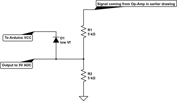
You can also protect your output by adding a diode to VCC (the Arduino's internal power supply), which has one big advantage: If the Arduino's voltage falls, at turn off or because of a heavy load, the protection voltage will fall with it. The best diode would be one with a low forward voltage, such as a Schottky.
Schottky diodes aren't always the best choice, by the way, because they usually have a higher reverse leak current. But since we are working with a 1mA signal in the last schematic, the leakage would have to be more than 10uA to be really noticeable and most diodes rated for 20V or more, when blocking only 5V fall well below that. But if your signal current through the resistors is very small, this is something to watch out for.
It would look like this:

I left out the op-amp, because I'm starting to get a bit lazy. I suspect it's still clear enough though.
You can use the Diode and the Zener both, but it should be sufficient to choose one.
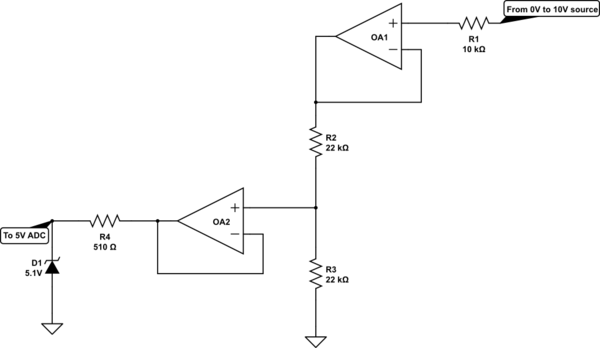
If your op-amp (final drawing/option) comes with two amps in one box, like with the 358, you could put the second one to good use to get your signal more accurate, especially in the case of the zener diode:

I have left out the power supply to the amps, but again, laziness sets in.
Now the first amp, again buffers the incoming signal, then the resistors divide that neatly by two, but that signal is then fed into another buffering op-amp. Because the input of the op-amp leaks nearly no current, in this case we can assume it to be zero, even for the adjusted resistors. That is why I made them larger: Wastes littler power. The second amp is again just a buffer, doesn't do anything else, so the signal stays the same, but "gets stronger".
Because the zener will try to clamp the output, we do need a protection resistor to keep the op-amp from melting. But, since this resistor can be very small compared to earlier designs you will notice much less of the little leak below it's rated voltage.
One problem though: Now the lower 1V of your 5V signal might get somewhat distorted, so while this helps the higher end stay neater, it will influence the lower end, because before it was the lower 1V of the input, which is 0.5V in the 5V output, or 10%. Now it has become 1V in your 5V output, which is the lower 20%, because there's also an op-amp in the 5V signal path that might not be perfect all the way at its lower supply voltage.
If you want the op-amps to be as perfect as possible from 0V to 5V output signal, you will always have to power them with -2V to -5V on their negative power supply, in stead of the GND of the system, but that requires a whole extra supply voltage.
Conclusion:
All the solutions in the drawings can be used in your situation, each has its own set of drawbacks (extra supply wires, more components, less safety, more distortion, etc) and advantages and what you think you can build and feel sufficient is up to you.
