added 2 characters in body
Source Link

So I have been studying resonant RLC-circuits, and have come to loaded Q-factors. At present I am trying to figure out the Q-factor of a circuit like this:
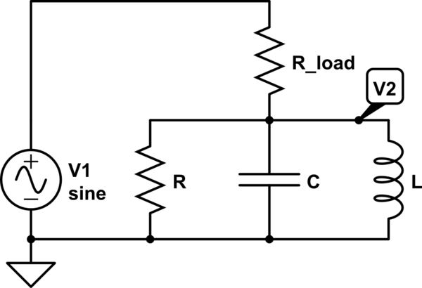
schematic

simulate this circuit – Schematic created using CircuitLab

My textbook (or lecture notes, rather) claims that the Q-factor of the above circuit will be \$Q_L =\omega_0 C (R // R_{load})\$, i.e. the same as if the load resistor was connected in parallel with the resonator. The only online resource I've found seems to agree (see page 5).

When I try to calculate the Q-factor I instead get

$$Q_L=2 \pi \frac{\mbox{Max energy stored}}{\mbox{Energy lost per cycle}} = 2 \pi \frac{v_2 C/2}{(v_1/\sqrt{2})^2/((R+R_{load})f_0)} = \omega_0 C (R_{load} + R) \left(\frac{R}{R+R_{load}}\right)^2=\omega_0 C \frac{R^2}{R+R_{load}}$$$$Q_L=2 \pi \frac{\mbox{Max energy stored}}{\mbox{Energy lost per cycle}} = 2 \pi \frac{v_2^2 C/2}{(v_1/\sqrt{2})^2/((R+R_{load})f_0)} = \omega_0 C (R_{load} + R) \left(\frac{R}{R+R_{load}}\right)^2=\omega_0 C \frac{R^2}{R+R_{load}}$$

since \$v_2 = \frac{R}{R+R_{load}}v_1\$ at resonance. Have I misunderstood the Q-factor, or messed up my reasoning somewhere?

So I have been studying resonant RLC-circuits, and have come to loaded Q-factors. At present I am trying to figure out the Q-factor of a circuit like this:

schematic

simulate this circuit – Schematic created using CircuitLab

My textbook (or lecture notes, rather) claims that the Q-factor of the above circuit will be \$Q_L =\omega_0 C (R // R_{load})\$, i.e. the same as if the load resistor was connected in parallel with the resonator. The only online resource I've found seems to agree (see page 5).

When I try to calculate the Q-factor I instead get

$$Q_L=2 \pi \frac{\mbox{Max energy stored}}{\mbox{Energy lost per cycle}} = 2 \pi \frac{v_2 C/2}{(v_1/\sqrt{2})^2/((R+R_{load})f_0)} = \omega_0 C (R_{load} + R) \left(\frac{R}{R+R_{load}}\right)^2=\omega_0 C \frac{R^2}{R+R_{load}}$$

since \$v_2 = \frac{R}{R+R_{load}}v_1\$ at resonance. Have I misunderstood the Q-factor, or messed up my reasoning somewhere?

So I have been studying resonant RLC-circuits, and have come to loaded Q-factors. At present I am trying to figure out the Q-factor of a circuit like this:

schematic

simulate this circuit – Schematic created using CircuitLab

My textbook (or lecture notes, rather) claims that the Q-factor of the above circuit will be \$Q_L =\omega_0 C (R // R_{load})\$, i.e. the same as if the load resistor was connected in parallel with the resonator. The only online resource I've found seems to agree (see page 5).

When I try to calculate the Q-factor I instead get

$$Q_L=2 \pi \frac{\mbox{Max energy stored}}{\mbox{Energy lost per cycle}} = 2 \pi \frac{v_2^2 C/2}{(v_1/\sqrt{2})^2/((R+R_{load})f_0)} = \omega_0 C (R_{load} + R) \left(\frac{R}{R+R_{load}}\right)^2=\omega_0 C \frac{R^2}{R+R_{load}}$$

since \$v_2 = \frac{R}{R+R_{load}}v_1\$ at resonance. Have I misunderstood the Q-factor, or messed up my reasoning somewhere?

deleted 66 characters in body
Source Link

So I have been studying resonant RLC-circuits, and have come to loaded Q-factors. At present I am trying to figure out the Q-factor of a circuit like this:

schematic

simulate this circuit – Schematic created using CircuitLab

Now, without the load the Q-factor will be \$Q_U =\omega_0 C R\$. My textbook (or lecture notes, rather) claims that the Q-factor of the above circuit will be \$Q_L =\omega_0 C (R // R_{load})\$, i.e. the same as if the load resistor was connected in parallel with the resonator. The only online resource I've found seems to agree (see page 5).

When I try to calculate the Q-factor I instead get

$$Q_L=2 \pi \frac{\mbox{Max energy stored}}{\mbox{Energy lost per cycle}} = 2 \pi \frac{v_2 C/2}{(v_1/\sqrt{2})^2/((R+R_{load})f_0)} = \omega_0 C (R_{load} + R) \left(\frac{R}{R+R_{load}}\right)^2=\omega_0 C \frac{R^2}{R+R_{load}}$$

since \$v_2 = \frac{R}{R+R_{load}}v_1\$ at resonance. Have I misunderstood the Q-factor, or messed up my reasoning somewhere?

So I have been studying resonant RLC-circuits, and have come to loaded Q-factors. At present I am trying to figure out the Q-factor of a circuit like this:

schematic

simulate this circuit – Schematic created using CircuitLab

My textbook (or lecture notes, rather) claims that the Q-factor of the above circuit will be \$Q_L =\omega_0 C (R // R_{load})\$, i.e. the same as if the load resistor was connected in parallel with the resonator. The only online resource I've found seems to agree (see page 5).

When I try to calculate the Q-factor I instead get

$$Q_L=2 \pi \frac{\mbox{Max energy stored}}{\mbox{Energy lost per cycle}} = 2 \pi \frac{v_2 C/2}{(v_1/\sqrt{2})^2/((R+R_{load})f_0)} = \omega_0 C (R_{load} + R) \left(\frac{R}{R+R_{load}}\right)^2=\omega_0 C \frac{R^2}{R+R_{load}}$$

since \$v_2 = \frac{R}{R+R_{load}}v_1\$ at resonance. Have I misunderstood the Q-factor, or messed up my reasoning somewhere?

Source Link

Loaded Q-factor of parallel RLC with series resistive load

So I have been studying resonant RLC-circuits, and have come to loaded Q-factors. At present I am trying to figure out the Q-factor of a circuit like this:

schematic

simulate this circuit – Schematic created using CircuitLab

Now, without the load the Q-factor will be \$Q_U =\omega_0 C R\$. My textbook (or lecture notes, rather) claims that the Q-factor of the above circuit will be \$Q_L =\omega_0 C (R // R_{load})\$, i.e. the same as if the load resistor was connected in parallel with the resonator. The only online resource I've found seems to agree (see page 5).

When I try to calculate the Q-factor I instead get

$$Q_L=2 \pi \frac{\mbox{Max energy stored}}{\mbox{Energy lost per cycle}} = 2 \pi \frac{v_2 C/2}{(v_1/\sqrt{2})^2/((R+R_{load})f_0)} = \omega_0 C (R_{load} + R) \left(\frac{R}{R+R_{load}}\right)^2=\omega_0 C \frac{R^2}{R+R_{load}}$$

since \$v_2 = \frac{R}{R+R_{load}}v_1\$ at resonance. Have I misunderstood the Q-factor, or messed up my reasoning somewhere?