1
\$\begingroup\$

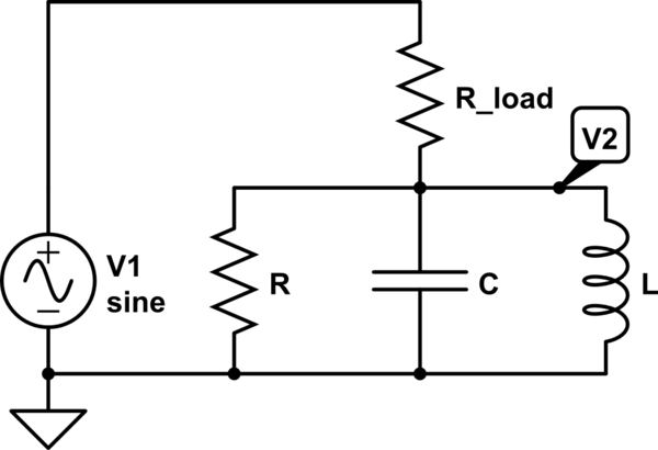
So I have been studying resonant RLC-circuits, and have come to loaded Q-factors. At present I am trying to figure out the Q-factor of a circuit like this:

schematic

simulate this circuit – Schematic created using CircuitLab

My textbook (or lecture notes, rather) claims that the Q-factor of the above circuit will be \$Q_L =\omega_0 C (R // R_{load})\$, i.e. the same as if the load resistor was connected in parallel with the resonator. The only online resource I've found seems to agree (see page 5).

When I try to calculate the Q-factor I instead get

$$Q_L=2 \pi \frac{\mbox{Max energy stored}}{\mbox{Energy lost per cycle}} = 2 \pi \frac{v_2^2 C/2}{(v_1/\sqrt{2})^2/((R+R_{load})f_0)} = \omega_0 C (R_{load} + R) \left(\frac{R}{R+R_{load}}\right)^2=\omega_0 C \frac{R^2}{R+R_{load}}$$

since \$v_2 = \frac{R}{R+R_{load}}v_1\$ at resonance. Have I misunderstood the Q-factor, or messed up my reasoning somewhere?

\$\endgroup\$
2
  • \$\begingroup\$ Read what you have put "without the load the Q-factor will be..." well of course it can't have the load as part of the equation can it? If the formula includes the load resistance then it is not the same thing as you calculated!! \$\endgroup\$
    – Andy aka
    Commented Nov 9, 2015 at 18:43
  • \$\begingroup\$ I'm not sure I understand what you mean. I have not edited out the unloaded part, since it's not really part of my question! \$\endgroup\$ Commented Nov 9, 2015 at 20:00

1 Answer 1

1
\$\begingroup\$

Regarding any AC analysis on this circuit, the effect of R and Rload are effectively in parallel and will therefore produce the same Q irrespective of whether their parallel value is in the feed position or the shunt position.

Think about the voltage source and its equivalent circuit with R and Rload - forget about L and C for the moment. Try this for size: -
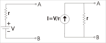
enter image description here

The two circuits are identical and the little_r resistor has changed to be across a current source. This puts it in parallel with any resistor across terminals A and B.

In fact if V1, Rload (or R1) were inside a box and you were not allowed to look inside, you could never know that what was contained was a voltage source in series with a resistor OR a current source in parallel with a resistor - there's no way of telling.

Here's an even more complex scenario: -
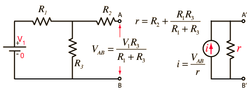
enter image description here

Now, if R2 were zero, the equivalent output impedance is the parallel arrangement of the two other resistors. Does that ring a bell?

It's called Norton's theorum - try googling it - also look up Thevenin's theorum - it operates in the reverse: -
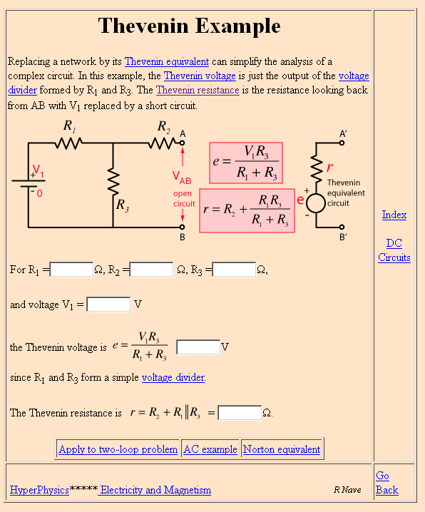
enter image description here

Picture stolen from here. Does this make sense now?

So if you agree that Q = \$\omega C R\$ then you know what value to use for R.


Calculating Q for a parallel LC fed by a voltage source via a resistor. Start with the impedance of a pure LC tuned circuit. This is: -

\$\dfrac{sL}{s^2LC+1}\$ then calculate what Vout would be i.e. the transfer function: -

H(s) = \$\dfrac{\dfrac{sL}{s^2LC+1}}{R + \dfrac{sL}{s^2LC+1}}\$

A bit of algebra and this becomes: -

\$\dfrac{\dfrac{s}{CR}}{s^2+\dfrac{1}{LC} +\dfrac{s}{CR}}\$

The bottom line is clearly (to some LOL) recognizable as the denominator in any damped resonant circuit where the various artefacts are: -
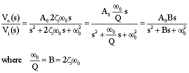
enter image description here

See this document and read the bandpass section to confirm. The above picture is an extract.

So \$2\zeta\omega_0 = \dfrac{1}{CR}\$ and, because Q is \$\dfrac{1}{2\zeta}\$, Q = \$CR\omega_0\$
\$\endgroup\$
4
  • \$\begingroup\$ Thanks for your reply, but I don't see how it answers my question. I was trying to calculate the Q-factor from the basic definition, in terms of energy lost and stored. \$\endgroup\$ Commented Nov 10, 2015 at 15:42
  • \$\begingroup\$ Well, once I naturalize both resistors into "R" I get Q = \$R\sqrt{\dfrac{C}{L}}\$ because at resonance Q is independant of omega or frequency. Maybe you mean omega to be the natural resonant frequency of the circuit i.e. \$\sqrt{\dfrac{1}{LC}}\$? Ah yes I see that you do but I calculate it in a way that might be alien to you. \$\endgroup\$
    – Andy aka
    Commented Nov 10, 2015 at 18:03
  • \$\begingroup\$ What exactly do you mean by naturalizing the resistors? \$\endgroup\$ Commented Nov 11, 2015 at 21:26
  • \$\begingroup\$ The first part of my answer is ALL about how you can take two seemingly different resistors and merge them into one value. I naturalized R and Rload into R and I gave you the proof that this is a perfectly legitimate operation on this type of circuit. \$\endgroup\$
    – Andy aka
    Commented Nov 11, 2015 at 21:49

Your Answer

By clicking “Post Your Answer”, you agree to our terms of service and acknowledge you have read our privacy policy.

Not the answer you're looking for? Browse other questions tagged or ask your own question.