It would be nice not to have to play "guess 1000 questions" and just have the real spec explained instead of sneaking up on it slowly, as we are doing now. If this is for a "hub odometer" type arrangement whose main aim is to measure wheel RPM then an easy and effective way is to have an internal "bob weight" which hangs down internally and does not rotate when the wheel does. The electronics then sense it going past a point on the PCB etc. This needs a mechanical bearing but this is very easy to do, easy to design and can be very long life indeed. The hub-odometer industry churns these out by the millions. This is THE easiest high output level simple arrangement if you can tolerate the bearing requirement.
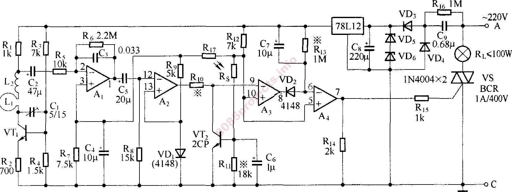
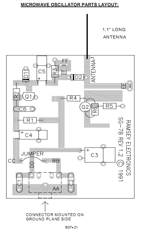
People have made electronic rotation sensing hubodometers for decades. Many of the methods mentioned by me and others could be made to work. A cyclical waveform that changes within cerain rate boundarioes can be extracted from the noise. eg an accelerometer can be arranged to be orthogonal (at 90 degrees) to "centrifugal" acceleration and will see cyclical gravity variation. Radar should be easy enough [tm] Note it may want to see wheel arches etc depending on where it is pointed.
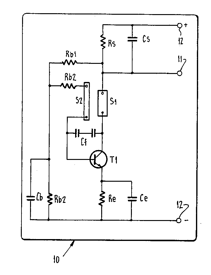
You MAY be able to do a differential capacitance sensor - or inductance. With two sensing "ends" at 180 degrees one will see road while other is seeing sky so signal will vary between two states with A-B at one monet and B-A 180 degres later. Even very low level signals can be extracted by autocorrelation or other means.


