There are a number of options. A few include:
Capacitive sensor - detects ground coming and going and allows a maximum to be detected.
As the ground is at a fixed angle to the wheel support structure, detecting when a point goes past a swing arm or fork or whatever will allow you to determine when another point is near the ground.
Sensor can then be inductive, magnetic etc.Optical sensor can detect ground proximity - either passive using daylight or by detecting eg an infrared beam.
Simple RADAR can do this well enough - this can be as simple as a few transistors.
Acoustic (usually ultrasonic) position detection can do this.
Magnetic detector determines wheel position using earth's magnetic field OR field of an attached magnet.
Hall sensor, fluxgate and similar measure field strength.
GMR. AMR and similar measure field angle.Two (or 3) orthogonal coils can detect position in space relative to a field.
Gyroscope (Mems)
More ...
Tell us what you REALLY want to do and we'll tell you how to do it :-).
_______________________-
Accelerometer:
Steven has mentioned accelerometer. I thought of this but left it out. These are relatively cheap and are readily available. But if this is on a vehicle (and that wheel is turning at a considerable speed for a vehicle if it is a normal wheel size) then accelerations due to turning and acceleration in various planes will make the job harder. You will still get a cyclic gravity variation of +/- 1g but it will be added to centripetal acceleration and turning, suspension and impact force effects. It MAY be the best solution, but some other that is not so affected by the vehicle dynamics is liable to be better.
RADAR
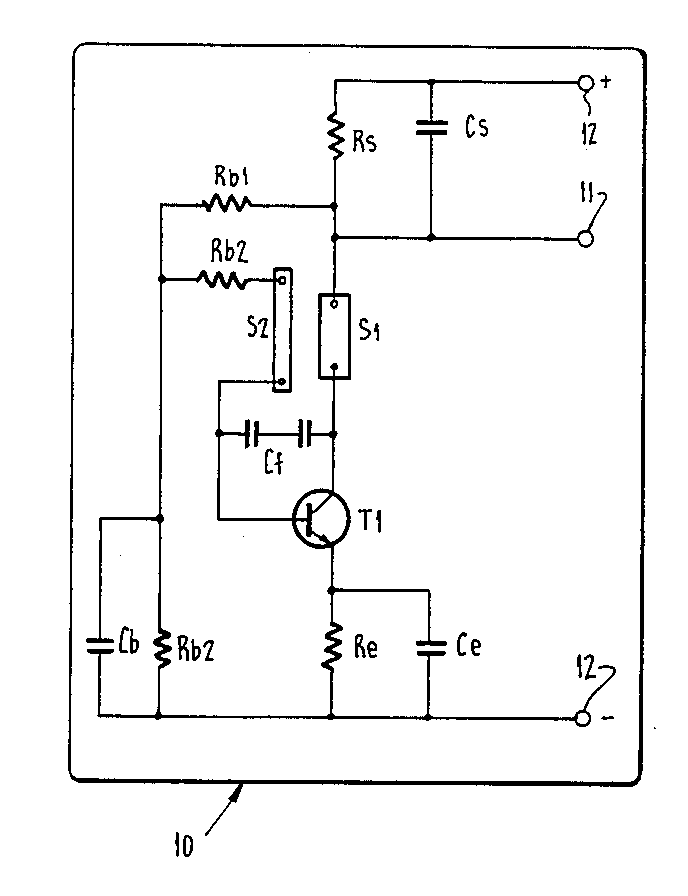
A Doppler RADAR may be implemented by using a self oscillating transistor or push pull pair at VHY or UHF to mix return signal with outgoing signal and return the difference frequency, which is the Doppler signal. The oscillator needs to be short term stable enough for the Doppler frequency difference to be detectable but can be less stable long term.
Here's a curcuit from someone pushing this to the limit. That's from US patent 4672379 - no guarantee of practicality as shown. I recall a hobby magazine in the last 20 years or so doing a self oscillating psuhpull pair with perhaps a diode detector. And Silicon Chip magazine (13 November 2006) published a RADAR speed gun project.

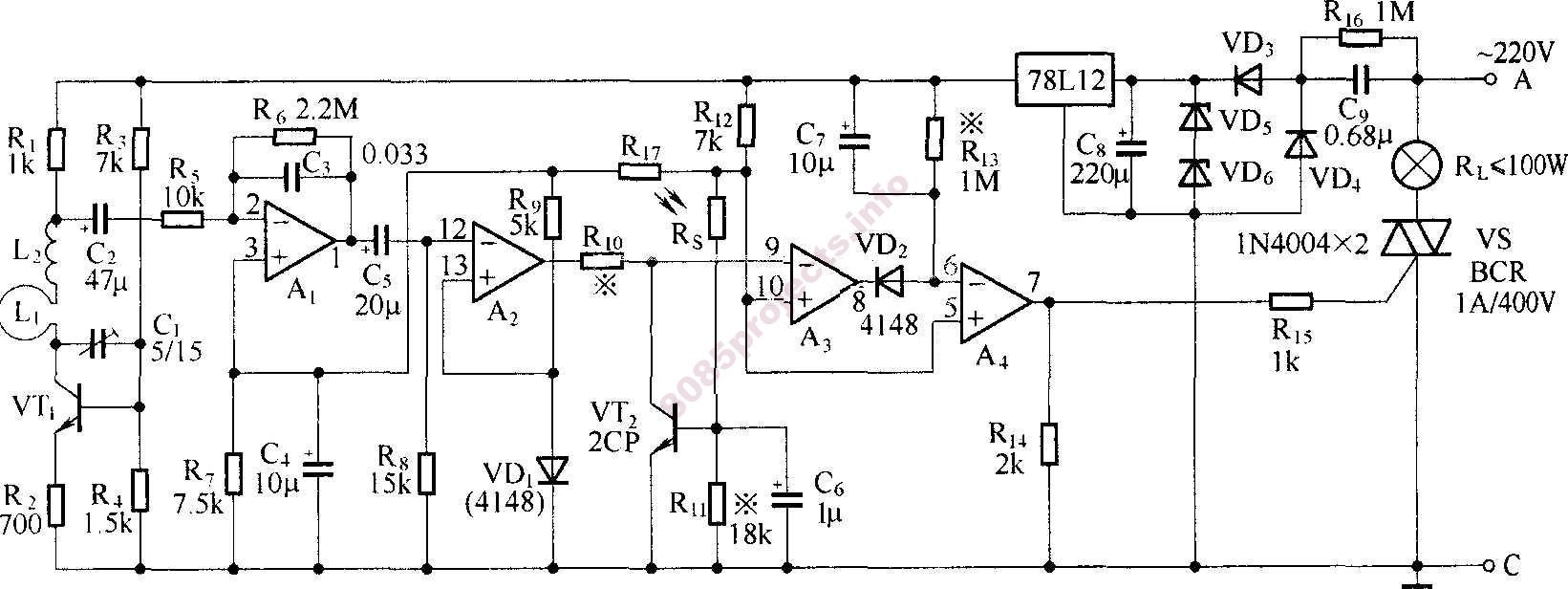
Here's a RADAR operated lamp circuit !
VT1 oscillates and receives. C couples the low frequency Doppler difference signal to amplifiers A1, buffered by A2, magic by A3 and rectified by A2 A3 then it is rectified by

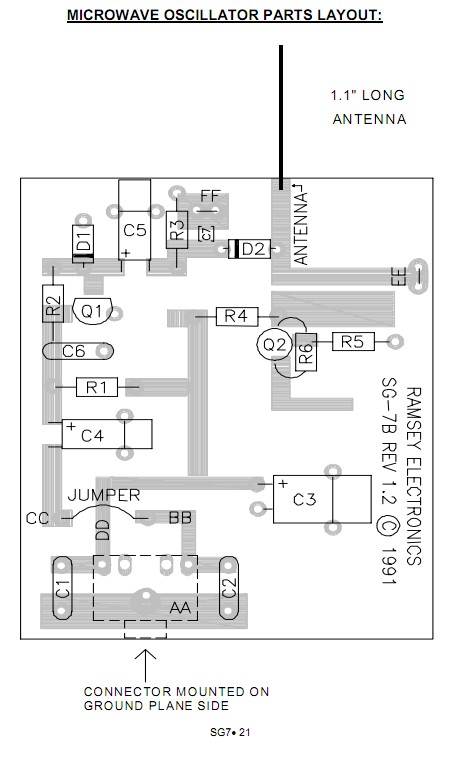
Here is an excellent assembly manual for Ramsey SG7 personal speed radar which does NOT have a circuit diagram but provides enough visual detail of the RF board for the very simple circuit of the RF transceiver and mixer to be easily traced out. Viz -

