This simple program for ATmega32A is expected to work in this way:
Set PORTC 0,1,2,3 as Output pins
Set PORTC 4, 5, 6, 7 as Input pins with pull ups
Turn on/off output pins 0, 1, 3:
3a. If input pin PORTC6 is HIGH turn 0, 1, 3 HIGH (5V)
3b. If input pin PORTC6 is LOW turn 0, 1, 3 LOW (0V)
 #define __DELAY_BACKWARD_COMPATIBLE__

 #ifndef F_CPU
 #define F_CPU 1000000UL    /* 1 MHz clock speed */
 #endif

 #include <avr/io.h>
 #include <util/delay.h>

 int
 main(void) {
     DDRC = 0x0F;    /* 00001111, set lower nibble of PORTC to OUTPUT, upper nibble to INPUT */
     PORTC = 0xFC;   /* set HIGH PORTC.3 and PORTC.2 00001100, Low PORTC.1 PORTC.0 and set pull-ups on all INPUT pins */

     while(1) {
         if (PINC & (1 << PC6)) { /* lets assume a 4V supply comes to PORTC.6 and Vcc = 5V */
             PORTC |= (1 << PC3);       /* 00001011 but don't touch PORT PC2 - it stays HIGH */
             PORTC |= (1 << PC1);       /* 00001011 but don't touch PORT PC2 - it stays HIGH */
             PORTC |= (1 << PC0);       /* 00001011 but don't touch PORT PC2 - it stays HIGH */
             _delay_ms(1000);    /* delay 1s */
         } else {
             PORTC &= ~(1 << PC3);       /* turn off all output pins */
             PORTC &= ~(1 << PC1);       /* turn off all output pins */
             PORTC &= ~(1 << PC0);       /* turn off all output pins */
             _delay_ms(1000);    /* delay 1s */
        }
     }
 }
I have built flash image and loaded this into MCU using avr-dude executing below commands:
avr-gcc -g -DF_CPU=1000000  -Wall -Os -Werror -Wextra -mmcu=atmega32a -Wa,-ahlmns=main.lst -c -o main.o main.c
avr-gcc -g -DF_CPU=1000000  -Wall -Os -Werror -Wextra -mmcu=atmega32a -o main.elf main.o
chmod a-x main.elf 2>&1
avr-objcopy -j .text -j .data -O ihex main.elf main.flash.hex
avr-objcopy -j .eeprom --set-section-flags=.eeprom="alloc,load" --change-section-lma .eeprom=0 -O ihex main.elf main.eeprom.hex
avr-objcopy: --change-section-lma .eeprom=0x0000000000000000 never used
avrdude -p m32 -cusbasp -B 5 -e -u -U flash:w:main.flash.hex

avrdude: set SCK frequency to 187500 Hz
avrdude: AVR device initialized and ready to accept instructions

Reading | ################################################## | 100% 0.00s

avrdude: Device signature = 0x1e9502
avrdude: erasing chip
avrdude: set SCK frequency to 187500 Hz
avrdude: reading input file "main.flash.hex"
avrdude: input file main.flash.hex auto detected as Intel Hex
avrdude: writing flash (176 bytes):

Writing | ################################################## | 100% 0.19s

avrdude: 176 bytes of flash written
avrdude: verifying flash memory against main.flash.hex:
avrdude: load data flash data from input file main.flash.hex:
avrdude: input file main.flash.hex auto detected as Intel Hex
avrdude: input file main.flash.hex contains 176 bytes
avrdude: reading on-chip flash data:

Reading | ################################################## | 100% 0.10s

avrdude: verifying ...
avrdude: 176 bytes of flash verified

avrdude done.  Thank you.
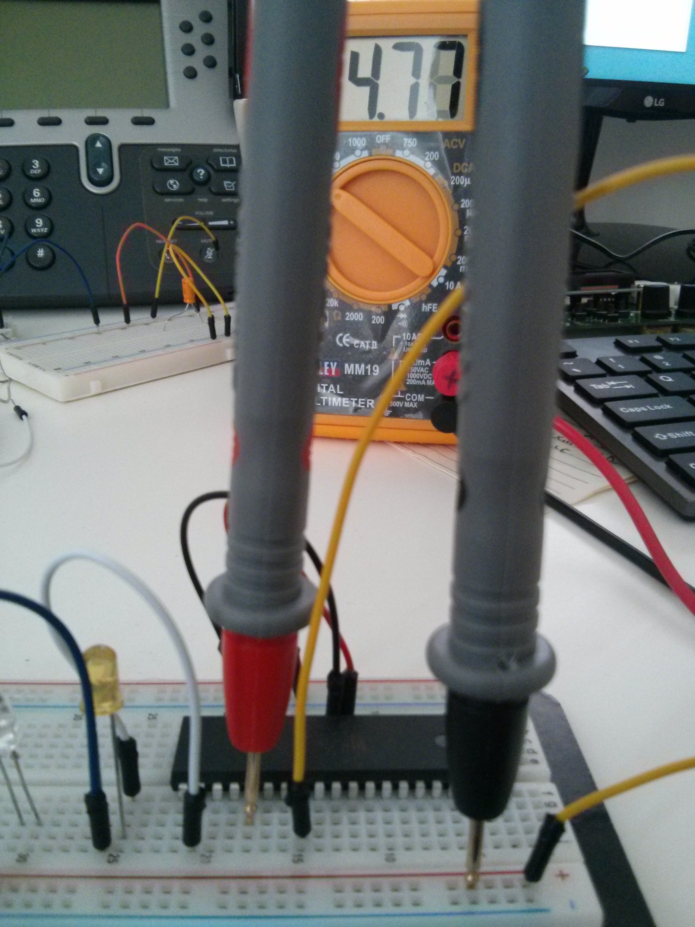
PORTC0 and PORTC1 work as expected and described above, when PORTC6 is LOW multimeter indicates voltage close to 0V, when PORTC6 goes HIGH the voltage is 4.92 - 4.98 V. The problem is PORTC3 doesn't work as expected. When it should be LOW multimeter shows 4.77 V

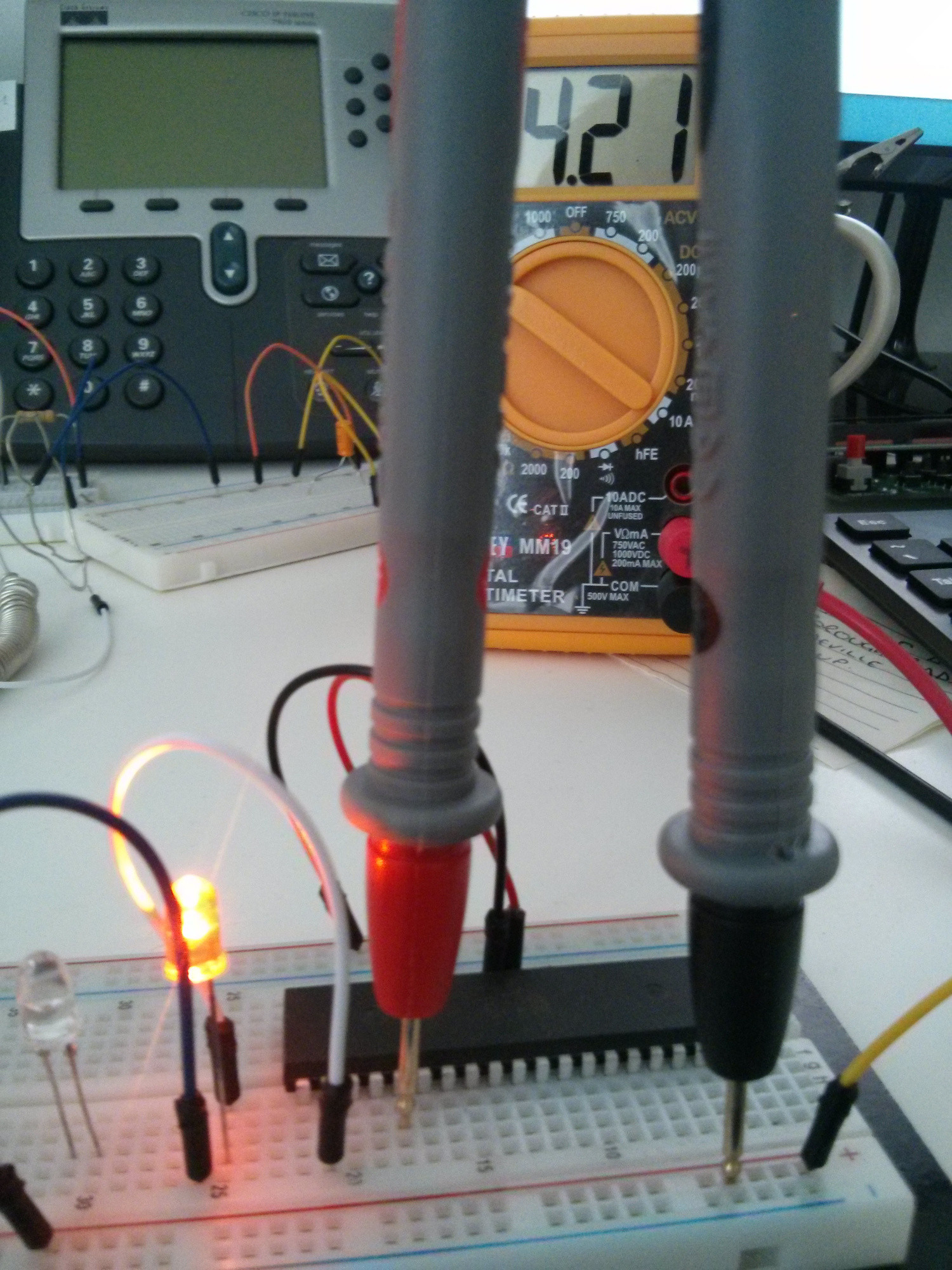
and when it should be HIGH it is 4.21 V (!):

Why it is so? Am I doing something wrong?