I have been given a small board which consists of 4 photodiodes and a [precision amplifier] 1.
To power the opamp I need to supply it with +2V and -37V according to the schematic I've been given.
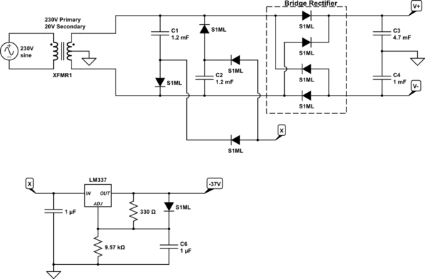
Below is the schematic of the power supply that supplies this board and I was having difficulty understanding it completely


simulate this circuitsimulate this circuit – Schematic created using CircuitLab
The parts I think I understand is the 4 diodes that make the bridge rectifier. C3 and C4 are ripple smoothing capacitors and that V+ will be ~28V~14V (20V10V x √2 - 0.7Vf) and V- will be ~-28V14V (-20V10V x √2 - 0.7Vf) although please correct me if I'm wrong.
The part I have trouble with is the voltage I've labelled 'X'. It has to be more negative than -37V otherwise the LM337 wouldn't be able to regulate it to -37V.
I'm going to make an assumption that it's something to do with C1 and C2 being connected to the AC input lines of the bridge made from the S1ML diodes connected to 'X' but I can't quite figure out the last bit myself.
