1
\$\begingroup\$

I have been given a small board which consists of 4 photodiodes and a precision amplifier.

To power the opamp I need to supply it with +2V and -37V according to the schematic I've been given.

Below is the schematic of the power supply that supplies this board and I was having difficulty understanding it completely
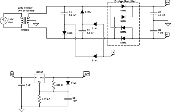
schematic

simulate this circuit – Schematic created using CircuitLab

The parts I think I understand is the 4 diodes that make the bridge rectifier. C3 and C4 are ripple smoothing capacitors and that V+ will be ~14V (10V x √2 - 0.7Vf) and V- will be ~-14V (-10V x √2 - 0.7Vf) although please correct me if I'm wrong.

The part I have trouble with is the voltage I've labelled 'X'. It has to be more negative than -37V otherwise the LM337 wouldn't be able to regulate it to -37V.

I'm going to make an assumption that it's something to do with C1 and C2 being connected to the AC input lines of the bridge made from the S1ML diodes connected to 'X' but I can't quite figure out the last bit myself.

\$\endgroup\$
2
  • 1
    \$\begingroup\$ Are we missing a centre-tap on the transformer secondary? \$\endgroup\$
    – Transistor
    Commented Jul 29, 2016 at 16:47
  • \$\begingroup\$ @Transistor its two 10V secondarys centre tapped to ground. I'll update it \$\endgroup\$
    – user103993
    Commented Jul 29, 2016 at 19:10

2 Answers 2

3
\$\begingroup\$

schematic

simulate this circuit – Schematic created using CircuitLab

Figure 1. (a) Charging the C1. (b) Transferring charge to C2.

For simplicity I will ignore all diode drops in this explanation.

  • The 10 V secondaries of your transformer will peak to \$ +10 \sqrt{2}~V \$ and \$ -10 \sqrt{2}~V \$.
  • At peak voltage the top end of C1 will be at +14 V and the bottom will be pulled to -14 V via D3. The capacitor will be charged to 28 V.
  • As the polarity reverses the voltage at the top of C1 is pulled down. The voltage at the bottom will attempt to maintain the 28 V difference. D3 will be reverse biased and will effectively be out of circuit (Figure 1b).
  • As the top of C1 reaches -14 V the bottom will have been pushed down to -42 V.
  • C2 will charge to -42 V via D6.

Your circuit has two of these charge pumps running on alternate half-cycles to improve the output current. Drop a few volts for the diodes and you've still got enough to run the LM337.

\$\endgroup\$
2
  • \$\begingroup\$ Is "charge pump" the term used for this sort of circuit? Is this a sort of AC equivalent to a boost converter? \$\endgroup\$
    – user103993
    Commented Jul 30, 2016 at 17:14
  • \$\begingroup\$ Yes, it is a charge pump. The principle of operation is different to a boost converter. This is using the "natural" alternation of the AC supply voltage and is passive. The boost converter needs active electronics and is inductive and current driven whereas this is capacitive and voltage driven. Thank you for accepting my answer. \$\endgroup\$
    – Transistor
    Commented Jul 30, 2016 at 17:20
0
\$\begingroup\$

Looks like voltage summing, from common reference between C3 and C4 -14V being added. Check Voltage multiplier

BTW, there are 2 diode voltage drops at rectifier.

\$\endgroup\$

Your Answer

By clicking “Post Your Answer”, you agree to our terms of service and acknowledge you have read our privacy policy.