added notes
Source Link
jonk
  • 78.7k
  • 6
  • 81
  • 195

You really should want some hysteresis as well as signal conditioning to your Arduino input levels. I'll get to that near the end.

I don't know what's powering your Arduino. If you are supplying it through an inexpensive \$5\:\textrm{V}\$ converter that works off the automotive voltage rail, you may find that it protect your Arduino from periodic load dumps.

Assuming you have a clean and safe \$5\:\textrm{V}\$ supply for the Ardiuno, then your main worry is if your Arduino I/O pin gets exposed to an external voltage (relative to the ground, of course) that is above the \$5\:\textrm{V}\$ supply rail. In such cases, the protection diodes will kick in and start leaking current into the supply rail. On most processors I've used before, I find that observing a maximum of \$2\:\textrm{mA}\$ meets the absolute maximum specifications. However, you may need to look up your specific processor to get the actual value for it. Since you didn't mention the exact Arduino board, I can't look it up for you. But the following circuit should be entirely safe to use and is easy to make.
schematicschematic

simulate this circuitsimulate this circuit – Schematic created using CircuitLab

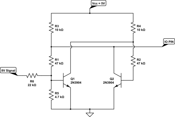
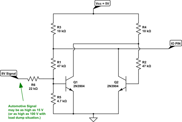
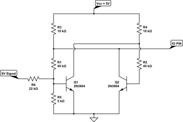
The above circuit uses two very cheap BJTs to create the hysteresis and the desired output signal. The output to the I/O pin is low when your signal is low and is high when the signal rises over about \$3.9\:\textrm{V}\$ (rising direction.) In the falling direction, the signal must go below about \$2\:\textrm{V}\$ for the output to return low. So the circuit includes a hysteresis band that is almost \$2\:\textrm{V}\$ wide, centered over about \$3\:\textrm{V}\$. So, good noise tolerance.

\$R_6\$ (and \$R_5\$) provides plenty of protection, as well. You could add a zener. But I don't think it's needed. In the case of supplying \$15\:\textrm{V}\$ to the signal input, the \$Q_1\$ base will experience about \$400\:\mu\textrm{A}\$ of base current. Which should be just fine. Even with \$100\:\textrm{V}\$ at the signal input \$Q_1\$'s base still sees only \$4\:\textrm{mA}\$. And either way, the I/O pin is protected. (Even if \$Q_1\$ completely fried all pins short for some reason.)

It also should be plenty fast enough for your needs.

You really should want some hysteresis as well as signal conditioning to your Arduino input levels. I'll get to that near the end.

I don't know what's powering your Arduino. If you are supplying it through an inexpensive \$5\:\textrm{V}\$ converter that works off the automotive voltage rail, you may find that it protect your Arduino from periodic load dumps.

Assuming you have a clean and safe \$5\:\textrm{V}\$ supply for the Ardiuno, then your main worry is if your Arduino I/O pin gets exposed to an external voltage (relative to the ground, of course) that is above the \$5\:\textrm{V}\$ supply rail. In such cases, the protection diodes will kick in and start leaking current into the supply rail. On most processors I've used before, I find that observing a maximum of \$2\:\textrm{mA}\$ meets the absolute maximum specifications. However, you may need to look up your specific processor to get the actual value for it. Since you didn't mention the exact Arduino board, I can't look it up for you. But the following circuit should be entirely safe to use and is easy to make.

schematic

simulate this circuit – Schematic created using CircuitLab

The above circuit uses two very cheap BJTs to create the hysteresis and the desired output signal. The output to the I/O pin is low when your signal is low and is high when the signal rises over about \$3.9\:\textrm{V}\$ (rising direction.) In the falling direction, the signal must go below about \$2\:\textrm{V}\$ for the output to return low. So the circuit includes a hysteresis band that is almost \$2\:\textrm{V}\$ wide, centered over about \$3\:\textrm{V}\$. So, good noise tolerance.

\$R_6\$ (and \$R_5\$) provides plenty of protection, as well. You could add a zener. But I don't think it's needed.

You really should want some hysteresis as well as signal conditioning to your Arduino input levels. I'll get to that near the end.

I don't know what's powering your Arduino. If you are supplying it through an inexpensive \$5\:\textrm{V}\$ converter that works off the automotive voltage rail, you may find that it protect your Arduino from periodic load dumps.

Assuming you have a clean and safe \$5\:\textrm{V}\$ supply for the Ardiuno, then your main worry is if your Arduino I/O pin gets exposed to an external voltage (relative to the ground, of course) that is above the \$5\:\textrm{V}\$ supply rail. In such cases, the protection diodes will kick in and start leaking current into the supply rail. On most processors I've used before, I find that observing a maximum of \$2\:\textrm{mA}\$ meets the absolute maximum specifications. However, you may need to look up your specific processor to get the actual value for it. Since you didn't mention the exact Arduino board, I can't look it up for you. But the following circuit should be entirely safe to use and is easy to make.

schematic

simulate this circuit – Schematic created using CircuitLab

The above circuit uses two very cheap BJTs to create the hysteresis and the desired output signal. The output to the I/O pin is low when your signal is low and is high when the signal rises over about \$3.9\:\textrm{V}\$ (rising direction.) In the falling direction, the signal must go below about \$2\:\textrm{V}\$ for the output to return low. So the circuit includes a hysteresis band that is almost \$2\:\textrm{V}\$ wide, centered over about \$3\:\textrm{V}\$. So, good noise tolerance.

\$R_6\$ (and \$R_5\$) provides plenty of protection, as well. You could add a zener. But I don't think it's needed. In the case of supplying \$15\:\textrm{V}\$ to the signal input, the \$Q_1\$ base will experience about \$400\:\mu\textrm{A}\$ of base current. Which should be just fine. Even with \$100\:\textrm{V}\$ at the signal input \$Q_1\$'s base still sees only \$4\:\textrm{mA}\$. And either way, the I/O pin is protected. (Even if \$Q_1\$ completely fried all pins short for some reason.)

It also should be plenty fast enough for your needs.
fixed quantities
Source Link
jonk
  • 78.7k
  • 6
  • 81
  • 195

You really should want some hysteresis as well as signal conditioning to your Arduino input levels. I'll get to that near the end.

(I I don't know what's powering your Arduino. If you are supplying it through an inexpensive \$5\:\textrm{V}\$ converter that works off the automotive voltage rail, you may find that it protect your Arduino from periodic load dumps.)

Assuming you have a clean and safe \$5\:\textrm{V}\$ supply for the Ardiuno, then your main worry is if your Arduino I/O pin gets exposed to an external voltage (relative to the ground, of course) that is above the \$5\:\textrm{V}\$ supply rail. In such cases, the protection diodes will kick in and start leaking current into the supply rail. On most processors I've used before, I find that observing a maximum of \$2\:\textrm{mA}\$ meets the absolute maximum specifications. However, you may need to look up your specific processor to get the actual value for it. Since you didn't mention the exact Arduino board, I can't look it up for you. But the following circuit should be entirely safe to use and is easy to make.

schematicschematic

simulate this circuitsimulate this circuit – Schematic created using CircuitLab

The above circuit uses two very cheap BJTs to create the hysteresis and the desired output signal. The output to the I/O pin is low when your signal is low and is high when the signal rises over about \$3.9\:\textrm{V}\$ (rising direction.) In the falling direction, the signal must go below about \$2\:\textrm{V}\$ for the output to return low. So the circuit includes a hysteresis band that is almost \$2\:\textrm{V}\$ wide, centered over about \$2.8\:\textrm{V}\$\$3\:\textrm{V}\$. So, good noise tolerance.

\$R_6\$ (and \$R_5\$) provides plenty of protection, tooas well. You could add a zener. But I don't think it's needed.

You really should want some hysteresis as well as signal conditioning to your Arduino input levels.

(I don't know what's powering your Arduino. If you are supplying it through an inexpensive \$5\:\textrm{V}\$ converter that works off the automotive voltage rail, you may find that it protect your Arduino from periodic load dumps.)

Assuming you have a clean and safe \$5\:\textrm{V}\$ supply for the Ardiuno, then your main worry is if your Arduino I/O pin gets exposed to an external voltage (relative to the ground, of course) that is above the \$5\:\textrm{V}\$ supply rail. In such cases, the protection diodes will kick in and start leaking current into the supply rail. On most processors I've used before, I find that observing a maximum of \$2\:\textrm{mA}\$ meets the absolute maximum specifications. However, you may need to look up your specific processor to get the actual value for it. Since you didn't mention the exact Arduino board, I can't look it up for you. But the following circuit should be entirely safe to use and is easy to make.

schematic

simulate this circuit – Schematic created using CircuitLab

The circuit includes a hysteresis band that is \$2\:\textrm{V}\$ wide, centered over about \$2.8\:\textrm{V}\$. So good noise tolerance, too.

You really should want some hysteresis as well as signal conditioning to your Arduino input levels. I'll get to that near the end.

I don't know what's powering your Arduino. If you are supplying it through an inexpensive \$5\:\textrm{V}\$ converter that works off the automotive voltage rail, you may find that it protect your Arduino from periodic load dumps.

Assuming you have a clean and safe \$5\:\textrm{V}\$ supply for the Ardiuno, then your main worry is if your Arduino I/O pin gets exposed to an external voltage (relative to the ground, of course) that is above the \$5\:\textrm{V}\$ supply rail. In such cases, the protection diodes will kick in and start leaking current into the supply rail. On most processors I've used before, I find that observing a maximum of \$2\:\textrm{mA}\$ meets the absolute maximum specifications. However, you may need to look up your specific processor to get the actual value for it. Since you didn't mention the exact Arduino board, I can't look it up for you. But the following circuit should be entirely safe to use and is easy to make.

schematic

simulate this circuit – Schematic created using CircuitLab

The above circuit uses two very cheap BJTs to create the hysteresis and the desired output signal. The output to the I/O pin is low when your signal is low and is high when the signal rises over about \$3.9\:\textrm{V}\$ (rising direction.) In the falling direction, the signal must go below about \$2\:\textrm{V}\$ for the output to return low. So the circuit includes a hysteresis band that is almost \$2\:\textrm{V}\$ wide, centered over about \$3\:\textrm{V}\$. So, good noise tolerance.

\$R_6\$ (and \$R_5\$) provides plenty of protection, as well. You could add a zener. But I don't think it's needed.

Source Link
jonk
  • 78.7k
  • 6
  • 81
  • 195

You really should want some hysteresis as well as signal conditioning to your Arduino input levels.

(I don't know what's powering your Arduino. If you are supplying it through an inexpensive \$5\:\textrm{V}\$ converter that works off the automotive voltage rail, you may find that it protect your Arduino from periodic load dumps.)

Assuming you have a clean and safe \$5\:\textrm{V}\$ supply for the Ardiuno, then your main worry is if your Arduino I/O pin gets exposed to an external voltage (relative to the ground, of course) that is above the \$5\:\textrm{V}\$ supply rail. In such cases, the protection diodes will kick in and start leaking current into the supply rail. On most processors I've used before, I find that observing a maximum of \$2\:\textrm{mA}\$ meets the absolute maximum specifications. However, you may need to look up your specific processor to get the actual value for it. Since you didn't mention the exact Arduino board, I can't look it up for you. But the following circuit should be entirely safe to use and is easy to make.

schematic

simulate this circuit – Schematic created using CircuitLab

The circuit includes a hysteresis band that is \$2\:\textrm{V}\$ wide, centered over about \$2.8\:\textrm{V}\$. So good noise tolerance, too.