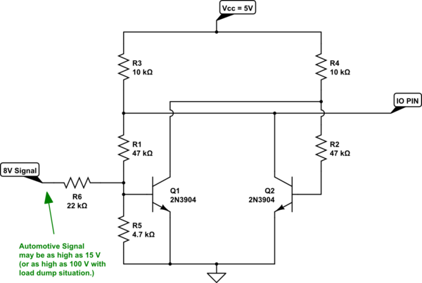
You really should want some hysteresis as well as signal conditioning to your Arduino input levels. I'll get to that near the end.
I don't know what's powering your Arduino. If you are supplying it through an inexpensive \$5\:\textrm{V}\$ converter that works off the automotive voltage rail, you may find that it protect your Arduino from periodic load dumps.
Assuming you have a clean and safe \$5\:\textrm{V}\$ supply for the Ardiuno, then your main worry is if your Arduino I/O pin gets exposed to an external voltage (relative to the ground, of course) that is above the \$5\:\textrm{V}\$ supply rail. In such cases, the protection diodes will kick in and start leaking current into the supply rail. On most processors I've used before, I find that observing a maximum of \$2\:\textrm{mA}\$ meets the absolute maximum specifications. However, you may need to look up your specific processor to get the actual value for it. Since you didn't mention the exact Arduino board, I can't look it up for you. But the following circuit should be entirely safe to use and is easy to make.

simulate this circuit – Schematic created using CircuitLab
The above circuit uses two very cheap BJTs to create the hysteresis and the desired output signal. The output to the I/O pin is low when your signal is low and is high when the signal rises over about \$3.9\:\textrm{V}\$ (rising direction.) In the falling direction, the signal must go below about \$2\:\textrm{V}\$ for the output to return low. So the circuit includes a hysteresis band that is almost \$2\:\textrm{V}\$ wide, centered over about \$3\:\textrm{V}\$. So, good noise tolerance.
\$R_6\$ (and \$R_5\$) provides plenty of protection, as well. You could add a zener. But I don't think it's needed. In the case of supplying \$15\:\textrm{V}\$ to the signal input, the \$Q_1\$ base will experience about \$400\:\mu\textrm{A}\$ of base current. Which should be just fine. Even with \$100\:\textrm{V}\$ at the signal input \$Q_1\$'s base still sees only \$4\:\textrm{mA}\$. And either way, the I/O pin is protected. (Even if \$Q_1\$ completely fried all pins short for some reason.)
It also should be plenty fast enough for your needs.
