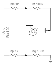
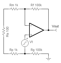
The current noise is probably irrelevant for an FET-input op-amp, so we can skip to calculating the output noise: Just multiply the input noise by the gain of the amplifier. However, you need to multiply by the "noise gain", not the signal gain. To find the noise gain of the amp, convert your existing sources into short circuits and put a test voltage source right in series with the non-inverting input of the amp:
To calculate the effect of the op-amp's current noise, take the current noise and multiply it by the equivalent resistance calculated earlier. For the TLC071, this is 0.6 fA/√Hz. So, combined with \$R_\mathrm{eq}\$ of 2.1 kΩ, we get 0.00126 nV/√Hz. Obviously this is much smaller than the op-amp's voltage noise, so it will have no effect on the result in this example. In cases with large \$R_\mathrm{eq}\$, it will have an effect. You can calculate it this way and combine it with the other sources as shown above:
$$
v_\mathrm{total}=\sqrt{{v_\mathrm{R}}^2+{v_\mathrm{V}}^2+{v_\mathrm{I}}^2}
$$
Also likely to have an effect is the bandwidth of your measurement equipment. The previous measurements assume a brickwall filter at 22 kHz, but brickwall filters can't exist in reality. You can correct for the fall-off of a real-life filter by calculating the equivalent noise bandwidth (ENBW). Here's a table of ENBW Filter correction factors vs order. See also Why are there two sets of ENBW correction factors?
In fact, voltage noise of the op-amp is not actually a constant. It varies with frequency, so is better written as \$\tilde v(f)\$. You can calculate it more accurately with numerical integration. See Noise and what does V/√Hz actually mean?


