Your calculation of the resistor power is in error (for your circuit 1). Even if you assume that the AC is turned on at the very worst possible moment, the RC time constant is low (0.01 s) so the capacitor charges quickly following the AC voltage. The major problem with the first circuit is that your signal is phase shifted, so it's not great as a zero crossing indicator.
The second circuit works ok, and provides a relatively stable reference, but it will be offset from the zero crossing. This is because you need a minimum current to get a signal (through the CTR of the opto) so the indicator is offset. If you want the signal to be closer to the zero crossing you need to lower the value of the resistor, which of course raises the power dissipated.
It surprises me that many folks still design using old established techniques, and not taking advantage of modern silicon solutions.
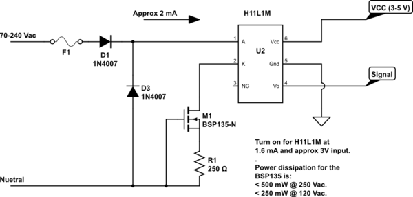
I designed the circuit below (big note: I have not built it yet), which uses a high voltage enhancementdepletion mode FET as a constant current source (this FET has nice binned characteristics). This allows you to turn on the signal to the microprocessor very close to the zero crossing. The FET replaces the resistors you would normally use and has to handle the power dissipation. However since it's constant current it turns on at a very low threshold voltage.
Here the worst case dissipation is under 0.5 W @ 250 Vac, and it would still provide quite accurate zero crossing indication down to under 20 Vac.
Any comments on the design welcome.

simulate this circuit – Schematic created using CircuitLab
