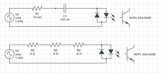
I am working on a project where a part of the circuit I have to design is sensing AC with microcontroller. As you can see below this cicruit is meant to operate with resistors, capacitors and an optocoupler.
Here are two designs I have in mind:

This circuit has to be reliable and last for a good amount of time (at least 5 years). The circuit will run only when the window shutter is moving which means the circuit will be mainly off.
In case I chose first design (preffered because of size limitations) I would use X class capacitor. Final value is yet to be determined.
The most problems I have is with the resistor. When the circuit turns ON / when AC (230 effective, 325 peak) voltage becomes present in the circuit, the current will only be limited by the resistors resistance before capacitors imedance kicks in. This means that the voltage across resistor will approximately be:
where worst case scenario AC ampliude is 325V (or more because of other factors) and Uf (diode forward voltage) will be 1.1V +/- 0.4V.
This means that for a brief moment power dissipated by the resistor will be more than 10.5W. I know that some resistors have graphs showing pulse powers. Should I even take this into account in my example?
I don't really know how long this pulse will last since I don't know how to simulate this, but I really think we are talking milliseconds or even less. Can anyone help me with this problem?
Would second circuit be more reliable than the first one? The heat sholdn't really be an issue since the sensing part of the circuit (which I'm showing here) isn't really supposed to work for long periods of time. Not even in minutes range. But like I said the 1st design is the one I would prefer.
Some additional info:
I've looked over several resistor types. I read MELF resistors are usually good to use where pulses are likely to occur though I would rather use thick film smd resistors which are easier to mount.
Resistor will be rated for 400V+ and after the capacitors impedance kicks in the power dissipated by the resistor will be aroun 1W which is quite some power but like I mentioned previously won't be lasting for a long time (I was hoping 1.5W resistor would do the job).
The optocoupler is probably going to be the one shown in the design. Optocouplers absolute maximum ratings: If = +/- 50mA, Ifsm = +/- 1A, I will try to stay in < 10mA range.
Generator frekuency does no reflect actual frequency the circuit will be exposed to. AC mains voltage: 230 effective / 325V peak, frequency: 50Hz


