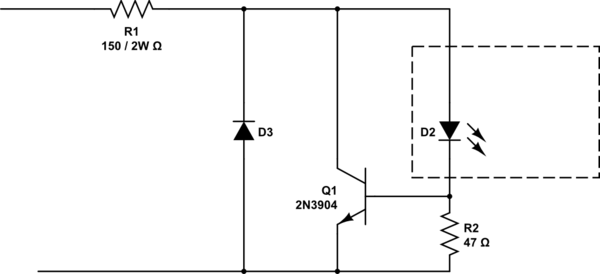
Something like this:

simulate this circuit – Schematic created using CircuitLab
EDIT: This circuit is a wide input control voltage. But what you have asked is an ESD protection for optocoupler. IMO you don't need it, the optos are tough devices.
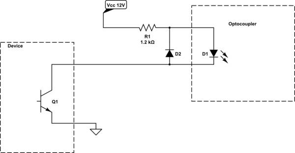
EDIT2: I am in PLC business for more than 15yrs. I had never seen a PLC with opto isolated input having TVS protection. The only failure I have seen was due wrong connection: 230VAC instead of 24VDC. 5m meter long wires are very short in automation world. A more probable failure that has to be expected is due to some contactor/relay kickback voltage, that is not equipped with freewheeling diode or MOV. In such case a negative spike will travel along your power supply. The reverse diode on the optocoupler is a must, or alternatively you can install an opto with bidirectional LED. It can provide you additional feature, if you want to use positive (PNP) or negative (NPN) logic.
EDIT3:
Your schematics is too complex. too many components. Here is a simpler one:

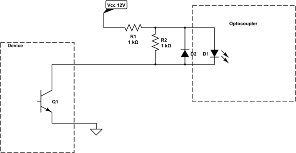
High speed with addition bleeding resistor, If LED = approx. 10mA:

